Section-1
www.newavenergy.com
04-1206_S1_NW_OPMPS_10-50kVA_GB_110201.doc
Page 13/20
Printed in Switzerland – Modifications reserved
UPS
Frames
B
a
tt
UPS
Frames
1.4.2.2 Positioning
UPS :
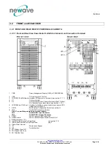
A minimum 200 mm rear space from the UPS to an obstruction is recommended for proper cooling as
the air enters at bottom/front and exits at unit rear (see Fig. 1 and 2)
External Battery :
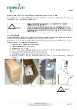
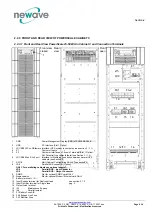
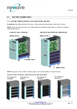
It’s recommended to install external battery cabinet(s) next to the UPS unit. The external
battery is recommended to be placed on left hand side of the UPS unit.
Check before the installation that the battery voltage values in the type plate of the UPS and external battery
cabinets are the same.
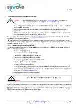
WARNING!
THE UPS CONTAINS HIGH DC VOLTAGES. A QUALIFIED PERSON MUST DO
THE CONNECTIONS BETWEEN THE UPS AND THE EXTERNAL BATTERY
CABINET(S). THE BATTERY CABINET IS CONNECTED ELECTRICALLY IN
PARALLEL WITH THE INTERNAL BATTERIES OF THE UPS.
WARNING!
IF AVAILABLE, THE INTERNAL BATTERY HAS TO BE DISCONNECTED
FIRST BECAUSE THE EXTERNAL
BATTERY TERMINALS ARE HAZARDOUS DUE TO THE PARALLEL
BATTERY STRING.
Battery Racks :
External battery racks shall be sized to take the voltage drop in the cable into account. To obtain
support and help contact the local office or agent authorized by the manufacturer.
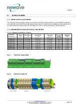
Clearances X Y
Minimum
200 mm
900 mm
UPS Frame type
Cabinet A
Cabinet B
Cabinet C
CBATT-C
Dimensions (WxHxD) mm
345x720x710 345x1045x710 440x1400x910 480x1400x940
Accessibility
Top / Rear / Right+Left side: Cabinet A & B
Top / Front / Right+Left: Cabinet C
Positioning
Min. 200 mm rear space (required for fan)
Input and Output Power Cabling
From the bottom on the rear side
X
X
Figure 1: UPS space recommendation
Figure 2 : UPS + Battery space recommendation
Y
Y


