New Yorker CG-A 30 Скачать руководство пользователя страница 10

10

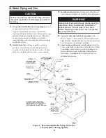
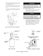
3. Mount vent damper assembly on draft hood without

modification to either. Refer to instructions packed
with vent damper for specific instructions. Vent
damper position indicator to be visible to users.

E

C

I

T

O

N

.

g

n

i

c

i

v

r

e

s

r

o

f

e

c

n

a

r

a

e

l

c

e

t

a

u

q

e

d

a

e

d

i

v

o

r

P

G

N

I

N

R

A

W

n

e

e

w

t

e

b

e

c

n

a

r

a

e

l

c

m

u

m

i

n

i

m

"

6

e

d

i

v

o

r

P

.

n

o

i

t

c

u

r

t

s

n

o

c

e

l

b

i

t

s

u

b

m

o

c

d

n

a

r

e

p

m

a

d

N

O

I

T

U

A

C

o

w

t

l

o

r

t

n

o

c

o

t

r

e

p

m

a

d

t

n

e

v

e

n

o

e

s

u

t

o

n

o

D

.

s

e

c

n

a

i

l

p

p

a

g

n

i

t

a

e

h

F.

Install Vent Connector

 from vent damper to chimney or

gas vent. See Figure 10.

1. Do not connect into same leg of chimney serving an

open fireplace.

2. Vent connector must not be smaller than vent

damper outlet. Type B is recommended, but single-
wall vent pipe may be used. Arrange venting system
so only the boiler is served by vent damper device.

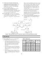
3. Where two or more appliances vent into a common

vent, the area of the common vent should be at least
equal to the area of the largest vent plus 50% of the
area in the additional vent(s). Do not connect the
vent of this appliance into any portion of mechanical
draft systems operating under positive pressure.

4. Vent connector should have greatest possible initial

rise above vent damper consistent with headroom
available and required clearance from adjacent
combustible building structure.

5. Vent connector should slope upward from vent

damper to chimney or gas vent not less than one
inch in four feet. No portion of vent connector
should run downward or have dips or sags. Vent
connector must be securely supported.

6. Vent connector should be installed above bottom of

chimney to prevent blockage. Inserted into but not
beyond inside wall of chimney liner. Seal tight
between vent connector and chimney.

G.

If an Existing Boiler is Removed:

When an existing boiler is removed from a common
venting system, the common venting system is likely to
be too large for proper venting of the appliances
remaining connected to it.
At the time of removal of an existing boiler, the
following steps shall be followed with each appliance
remaining connected to the common venting system
placed in operation, while the other appliances
remaining connected to the common venting system are
not in operation:
a. Seal any unused openings in the common venting

system.

b. Visually inspect the venting system for proper size

and horizontal pitch and determine there is no
blockage or restriction, leakage, corrosion, and other
deficiencies which could cause an unsafe condition.

c. Insofar as is practical, close all building doors and

windows and all doors between the space in which
the appliances remaining connected to the common
venting system are located and other spaces of the
building. Turn on clothes dryers and any appliance
not connected to the common venting system. Turn
on any exhaust fans, such as range-hoods and
bathroom exhausts, so they will operate at maximum
speed. Do not operate a summer exhaust fan. Close
fireplace dampers.

d. Place in operation the appliance being inspected.

Follow the Lighting (or Operating) Instructions.
Adjust thermostat so appliance will operate
continuously.

e. Test for spillage at the draft hood relief opening after

5 minutes of main burner operation. Use the flame of
a match or candle, or smoke from a cigarette, cigar or
pipe.

f. After it has been determined that each appliance

remaining connected to the common venting system
properly vents when tested as outlined above,
return doors, windows, exhaust fans, fireplace
dampers and any other gas-burning appliance to
their previous condition of use.

g. Any improper operation of the common venting

system should be corrected so the installation
conforms with the 

National Fuel Gas Code

, NFPA

54/ANSI Z223.1. When resizing any portion of the
common venting system, the common venting
system should be resized to approach the minimum
size as determined using the appropriate tables in
Part 11 in the 

National Fuel Gas Code

, NFPA 54/

ANSI Z223.1.

Содержание CG-A 30

Страница 1: ...INSTALLATION OPERATING AND SERVICE INSTRUCTIONS CLASSIC CG A SERIES GAS BOILER n o n o i t a m r o f n i g n i k e e s n e h W r o t c a r t n o c g n i t a e h r u o y l l a c r e l i o b o t s r i a p e r r o e c i v r e s r o F l e b a L g n i t a R n o n w o h s s a r e b m u N l a i r e S d n a r e b m u N l e d o M r e l i o B e d i v o r p r e l i o b r e b m u N l e d o M r e l i o B r e b...

Страница 2: ...C s n o l l a G x o r p p A g n i p p i h S t h g i e W b L d n u o R e r a u q S 0 3 2 1 1 2 2 1 6 4 4 3 5 4 2 1 8 2 1 4 5 1 x a i D 4 5 1 x 8 x 8 2 1 2 3 4 5 2 0 4 4 3 4 2 4 1 5 1 8 5 7 5 4 1 7 4 8 1 9 2 1 4 5 1 x a i D 5 5 1 x 8 x 8 2 1 4 8 9 2 0 5 8 2 2 1 8 1 4 1 9 6 8 5 8 4 4 3 9 2 1 4 5 1 x a i D 6 5 1 x 8 x 8 2 1 7 4 6 4 3 0 6 4 1 1 3 4 3 1 2 8 7 0 1 6 8 5 8 4 4 3 9 2 1 4 5 1 x a i D 6 5 1 ...

Страница 3: ...and Safety Devices for Automatically Fired Boilers ANSI ASME CSD 1 C Applianceisdesigncertifiedforinstallationon combustible flooring The boiler must not be installed on carpeting D Provideclearancebetweenboilerjacketand combustiblematerialinaccordancewithlocalfire ordinance RefertoFigure2forminimumclearancefrom combustible material for closet installation For alcove or unconfined space installati...

Страница 4: ...s u b m o c e t a u q e d A r e p o r p e r u s s a o t d e d i v o r p e b t s u m n o i t s u b m o c The following guideline is based on the National Fuel GasCode NFPA54 ANSIZ223 1 1 Determinevolumeofspace boilerroom Rooms communicating directly with space through openings not furnished with doors are considered part of space Volume ft Length ft xWidth ft xHeight ft 2 Determine Total Input of a...

Страница 5: ...uit Figure 3 Recommended Boiler Piping For Series Loop Hot Water Heating Systems C InstallSafetyReliefValve SeeFigure1 SafetyRelief Valve must be installed with spindle in vertical position G N I N R A W e b t s u m g n i p i p e g r a h c s i d e v l a v f e i l e r y t e f a S f o l a i t n e t o p e t a n i m i l e o t r o o l f r a e n d e p i p a e r a y n a n i e p i p t o n o D s n r u b e ...

Страница 6: ...til system water temperature reaches normal operating range Adjust valves to provide 180 to 200 F supply water temperature Opening the boiler supply valve will raise system temperature while opening by pass valve will lower system supply temperature I Ahotwaterboilerinstalledaboveradiationlevelmust be provided with a low water cutoff device as part of installation Figure 4 Recommended Piping for C...

Страница 7: ...f valve 2 Locate leaks using approved combustible gas detector soap and water or similar nonflammable solution Do not use matches candles open flames or other ignition source 4 Specific gravity of gas Gas piping systems for gas with a specific gravity of 0 70 or less can be sized directly from Table 3 unless authority having jurisdiction specifies a gravity factor be applied For specific gravity g...

Страница 8: ...ewallmetalvent AllowedbyANSIZ223 1 NFPA 54 under very restrictive conditions B Inspect chimney and remove any obstructions or restrictions Clean chimney if previously used for solid or liquid fuel burning appliances or fireplaces R E G N A D g n i l l a t s n i e r o f e b y e n m i h c g n i t s i x e t c e p s n I d e t a r o f r e p e c a l p e r r o n a e l c o t e r u l i a F r e l i o b r o ...

Страница 9: ...t Damper Carton and remove Installation Instructions Read Installation Instructions thoroughly before proceeding E C I T O N n o i t a l l a t s n i s n o i t a c i f i c e p s e h t o t r e f e r e s a e l P e d i u g g n i t o o h s e l b u o r t d n a s n o i t c u r t s n i r o f n o t r a c r e p m a d t n e v e h t n i d e k c a p s n o i t c u r t s n i n o i t a l l a t s n i d e l i a t e...

Страница 10: ...mmon venting system is likely to be too large for proper venting of the appliances remaining connected to it At the time of removal of an existing boiler the following steps shall be followed with each appliance remaining connected to the common venting system placed in operation while the other appliances remaining connected to the common venting system are not in operation a Seal any unused open...

Страница 11: ...by avoiding placement of furniture near thermostat VI Electrical D Wire thermostat Provide Class II circuit between thermostat and boiler Set thermostat heat anticipator to 0 3 amps See Figure 12 for continuous ignition standing pilot or Figure 13 for intermittent ignition EI If system tends to overheat above thermostat s temperature setting reduce heat anticipator setting by 0 1 or 0 2 amps If sy...

Страница 12: ... switch to Limit terminals T and TV See Paragraph G F Wire boiler Boiler is rated for 120 VAC 60 hertz less than 12 amperes Provide individual branch circuit with fused disconnect Connect to black and white wires and green ground screw See Figure 12 for continuous ignition standing pilot or Figure 13 for intermittent ignition EI N O I T U A C y a m h c i h w s l o r t n o c s n i a t n o c r e l i...

Страница 13: ...or heat If blocked vent switch is activated do not attempt to place boiler in operation The source of blockage must be corrected by trained and skilled personnel from a qualified service agency before resetting switch c FlameRoll outSwitch Automaticallyinterrupts boiler operation when flames or excessive heat are present in vestibule Circulator continues to operate and Vent Damper remains open wit...

Страница 14: ...ce agency before resetting switch c FlameRoll outSwitch Automaticallyinterrupts boiler operation when flames or excessive heat are present in vestibule Circulator continues to operate and Vent Damper remains open with call for heat Control is single use device If flame roll out switch is activated do not attempt to place boiler in operation The source of blockage must be corrected and the flame ro...

Страница 15: ...o 12 psi Leave globe valve open j Open isolation valve in boiler supply piping k Remove hose from bib cock 2 Turn ROOM THERMOSTAT to lowest setting 3 Be sure that gas to pilot and main burners has been off for at least five minutes and vent damper has been in the open position 4 Turn OFF the electric switch serving boiler 5 Open valve on main gas line at meter 6 PURGEAIRFROMGASPIPING Thisprocedure...

Страница 16: ...16 Figure 15 Operating Instructions ...

Страница 17: ...17 Figure 16 Lighting Instructions ...

Страница 18: ...e shown on Rating Label must not be exceeded Inlet pressure must not be lower than minimum inlet pressure shown on Rating Label 2 All Rate checks and all adjustments are to be made while boiler is firing all other appliances connected to the same meter as the boiler must be off 3 With boiler off water Manometer or water column gauge should be connected to a shut off cock installed in the 1 8 outle...

Страница 19: ...en temperature is indicated adjust limit to setting below observed temperature Main burners should extinguish 3 Adjust limit to setting above observed temperature Ignition sequence should begin 4 Adjust thermostat to lowest setting Adjust limit to desired setting J CheckThermostatOperation Raiseandlower temperature setting to start and stop boiler operation Adjust thermostat to normal setting K Co...

Страница 20: ...20 ...

Страница 21: ...21 ...

Страница 22: ...eal 5 Install flue baffles if used 6 Install new gasket material See Section IX Repair Parts Install canopy Secure with carriage bolts 7 Install Jacket Top Panel Draft Hood Blocked Vent Switch Vent Damper and vent pipe E CleanMainBurnersandFirebox 1 To remove burners for cleaning changing orifices or repairs a Remove Jacket Front Panel b Disconnect pilot tubing at gas valve c For Continuous Igniti...

Страница 23: ... must be in same location as original installation See Table 6 Burners must be properly located on support bracket at rear of burner Slide burner over orifice 7 For Continuous Ignition Standing Pilot connect thermocouple at gas valve For Intermittent Igntion EI connect pilot gas supply igniter cable sensor cable and ground wire at Ignition Module 8 Install Burner Access Panel Connect Flame Rollout...

Страница 24: ...ot To replace thermocouple a Loosen attachment nut securing thermocouple to pilot burner b Remove thermocouple Replace per Section IX Repair Parts 3 Intermittent Ignition EI To adjust or check spark gap between electrode and hood a Use round wire gauge to check spark gap b Spark gap should be 0 1 inch for optimum performance See Figure 22 4 To replace pilot burner assembly a Remove two machine scr...

Страница 25: ... 8 1 1 6 3 2 8 1 7 2 3 Q t e k c a r B t o l i P 5 4 h t i w r e n r u B n i a M P L t o l i P g n i d n a t S n o i t i n g I s u o u n i t n o C 0 2 1 6 3 2 8 1 1 1 1 1 1 1 9 9 J t e k c a r B t o l i P 0 6 h t i w r e n r u B n i a M P L r o l a r u t a N I E n o i t i n g I t n e t t i m r e t n I 8 1 1 6 3 2 8 1 1 1 1 1 1 d l o f i n a M 1 3 0 9 1 2 2 8 1 1 4 0 9 1 2 2 8 1 1 5 0 9 1 2 2 8 1 1...

Страница 26: ...1 1 s a G l a r u t a N 8 0 0 6 C 0 0 2 8 R V l l e w y e n o H e v l a V s a G 2 8 1 0 6 6 1 8 1 1 1 1 s a G l a r u t a N 4 3 1 4 C 0 0 3 8 R V l l e w y e n o H e v l a V s a G 3 8 1 0 6 6 1 8 1 1 e n a p o r P P L 0 4 0 6 C 0 0 2 8 R V l l e w y e n o H e v l a V s a G 3 4 2 0 6 6 1 8 1 1 1 1 e n a p o r P P L 8 4 5 4 C 0 0 3 8 R V l l e w y e n o H e v l a V s a G 4 4 2 0 6 6 1 8 1 1 8 8 9 1 ...

Страница 27: ...r e b m u N l e d o M A G C 0 3 0 4 0 5 0 6 0 7 0 8 e n a p o r P P L r o s a G l a r u t a N d o o H t f a r D 1 0 9 1 1 1 8 1 2 0 9 1 1 1 8 1 3 0 9 1 1 1 8 1 1 4 0 9 1 1 1 8 1 1 r e p m a D t n e V 4 1 2 3 6 1 1 8 1 5 2 2 3 6 1 1 8 1 6 3 2 3 6 1 1 8 1 1 7 4 2 3 6 1 1 8 1 1 ...

Страница 28: ...not be applicable if the boiler is used or operated over its rated capacity is installed for uses other than home heating or is not maintained in accordance with New Yorker s Installation Operating and Service Instructions and hydronics industry standards 5 Improper Operation These warranties will not be applicable if the boiler has been damaged as a result of being improperly serviced or operated...

Отзывы: