Network Technologies Xtendex USB-C5-200 Скачать руководство пользователя страница 8

NTI XTENDEX USB EXTENDER 


5


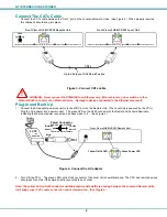
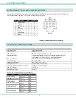
INTERCONNECTION CABLE WIRING METHOD 


The connection cable between the remote and local is terminated with RJ45 connectors and must be wired according to the 
EIA/TIA 568 B industry standard.   Wiring is per the table and drawing below.    


Pin 

Wire Color 

Pair 

Function 

 1 

White/Orange 

 2 

Orange 

 3 

White/Green 

 4 

Blue  1 

 5 

White/Blue 

 6 

Green 3 

 7 

White/Brown 

 8 

Brown 4 


                                                                                              Figure 5- View looking into RJ45 female 

TECHNICAL SPECIFICATIONS 


USB to host CPU 

USB Type B female 

USB to device 

USB Type A female 

USB output power 

5V, 1.4A for 4 ports (<500mA per port) 

Interconnect Cable 

CAT5e Solid/Stranded UTP/STP; CAT6 Solid or Stranded UTP/STP ;  

CAT6a Solid UTP; CAT7 Solid STP    EIA/TIA 568 B wiring 

Remote Unit Power 

100V to 240V at 50 or 60Hz-5VDC/3.0A via AC adapter        

Local Unit Power 

Powered by CPU 

Operating temperature 

32

°

F to 122

°

F (0

°

C to 50

°

C)


Storage temperature 

-20

°

F to 140

°

F (-30

°

C to 60

°

C)


Operating and Storage Relative Humidity 

0 to 90% non-condensing RH


Size  (In.)  WxDxH 

5.1x3.1x1.2   

Regulatory Approvals 

RoHS, CE 


Distances for CAT5e, CAT6(a) and CAT7 Cables 

Cable 

USB Device Type  Distance (ft)

USB 1.1/1.0 

180 

CAT5e Solid or 
Stranded, UTP or STP

  USB 2.0 

150 

USB 1.1/1.0 

180 

CAT6 Solid or 
Stranded, UTP or STP


USB 2.0 

150 

USB 1.1/1.0 

200 

CAT6a Solid UTP


USB 2.0 

180 

USB 1.1/1.0 

200 

CAT7 Solid SSTP


USB 2.0 

180 


T

1
+

R

2
-

T

3
+

R

4
-

T

5
+

R

6
-

T

7
+

R

8
-

Pair 2

Pair 1

Pair 4

Pair 3

Содержание Xtendex USB-C5-200

Страница 1: ...MAN026 Rev Date 8 27 2014 USB C5 200 200 Foot USB Extender Installation and Operation Manual XTENDEX Series Front and Rear View of USB C5 200 Remote Unit...

Страница 2: ...en consent of Network Technologies Inc 1275 Danner Drive Aurora Ohio 44202 CHANGES The material in this guide is for information only and is subject to change without notice Network Technologies Inc r...

Страница 3: ...The CATx Cable 4 Plug in and Boot Up 4 Interconnection Cable Wiring Method 5 Technical Specifications 5 Troubleshooting 6 Warranty Information 6 TABLE OF FIGURES Figure 1 Connect video and device cab...

Страница 4: ...1 specifications Supports low speed and full speed USB devices Supports Plug n Play specification MATERIALS Materials Included with this kit 9 NTI XTENDEX Local and Remote Unit 9 1 100VAC to 240VAC at...

Страница 5: ...ding equipment etc All cables should be installed in such a way that they do not cause stress on their connections to the equipment Extended lengths of cable hanging from a connection may interfere wi...

Страница 6: ...B male cable end to the USB Type B female connector on the Local Unit Figure 1 Connect device cable to the Local Unit Installing the Remote Unit Connect cables from the Remote Unit to the extended dev...

Страница 7: ...it See Figure 4 Figure 4 Connect the AC adapter 2 Turn ON the CPU The green LED on the RJ45 connector of the Local Unit should illuminate The CPU and remote devices should each react as if they were...

Страница 8: ...connect Cable CAT5e Solid Stranded UTP STP CAT6 Solid or Stranded UTP STP CAT6a Solid UTP CAT7 Solid STP EIA TIA 568 B wiring Remote Unit Power 100V to 240V at 50 or 60Hz 5VDC 3 0A via AC adapter Loca...

Страница 9: ...Problem Cause Solution Remote or Local Unit green power LED does not illuminate Power supply is not connected or plugged in Remote Unit CPU is not powered ON Local Unit Make sure outlet is live and A...

Отзывы: