


NTI XTENDEX USB EXTENDER
2
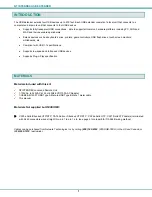
FEATURES AND FUNCTIONS
1.
5VDC- 3.0A
- connection jack for the AC adapter
2.
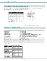
CAT 5
- RJ45 females- for connecting the CAT 5 cables
2a. Green LED- power indicator- illuminates when power has been supplied to the unit
2b. Yellow LED-traffic indicator- blinks when there is communication between the local and remote units
3.
USB
- Type A connectors- for connecting extended USB devices
4.
CPU USB
-Type B connector- for connecting to a USB connector on the CPU for USB device support
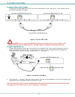
PREPARATION FOR INSTALLATION
•
Locations should be chosen for the mice, keyboards, and any other devices where there is also space to connect the Remote
and Local Units within the distance provided by the cables. If extension cables are needed, contact NTI for the cables
required.
•
The CATx cable must be run to the locations where the Remote and Local Units will be connected. Be careful to route the
cable away from any sources of magnetic fields or electrical interference that might reduce the quality of the extended signals
(i.e. AC motors, welding equipment, etc.).
•
All cables should be installed in such a way that they do not cause stress on their connections to the equipment. Extended
lengths of cable hanging from a connection may interfere with the quality of that connection. Secure cables as needed to
minimize this.
•
Properly shut down and disconnect the power from the CPU and devices to be separated. If other equipment is involved
whose connections are being interrupted, be sure to refer to the instruction manuals for that equipment for proper
disconnection and re-connection procedures before proceeding.
Note: CATx connection cable used between NTI XTENDEX Series Local and Remote or any XTENDEX Series products
should not be run underground, outdoors or between buildings.
WARNING: Outdoor or underground runs of CATx cable could be dangerous and will void the warranty.
1
3
4
1
2
3
4
USB DEVICES
CPU USB
NETWORK TECHNOLOGIES INC
Tel:330-562-7070
1275 Danner Dr, Aurora, OH 44202
www.networktechinc.com
5VDC
3A
-
+
CAT 5
CAT 5
NETWORK TECHNOLOGIES INC
Tel:330-562-7070
1275 Danner Dr, Aurora, OH 44202
www.networktechinc.com
2
2
2b
2a
Front View of USB-C5-200 Remote Unit
Rear View of USB-C5-200 Remote Unit
Front View of USB-C5-200 Local Unit
Rear View of USB-C5-200 Local Unit


