


NTI XTENDEX USB EXTENDER
3
INSTALLATION
Installing The Local Unit
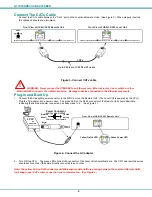
1.
Connect the USB2-AB-1M-5T USB cable from the Local Unit to the back of the CPU. (See Figure 1.)
a)
Connect the USB Type A male cable end to a USB Type A female connector on the CPU.
b)
Connect the USB Type B male cable end to the USB Type B female connector on the Local Unit.
Figure 1- Connect device cable to the Local Unit
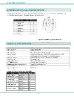
Installing the Remote Unit
Connect cables from the Remote Unit to the extended devices as shown below.
Figure 2- Connect extended devices to the Remote Unit
USB Flash Drive
USB Keyboard
USB MOUSE
USB CAMERA
1
2
3
4
USB DEVICES
Rear View of USB-C5-200 Remote Unit
USB PC, MAC
OR SUN CPU
USB Type A Male
USB Type B
Male
Rear View of USB-C5-200 Local Unit


