background image

Logs Configuration 

The 

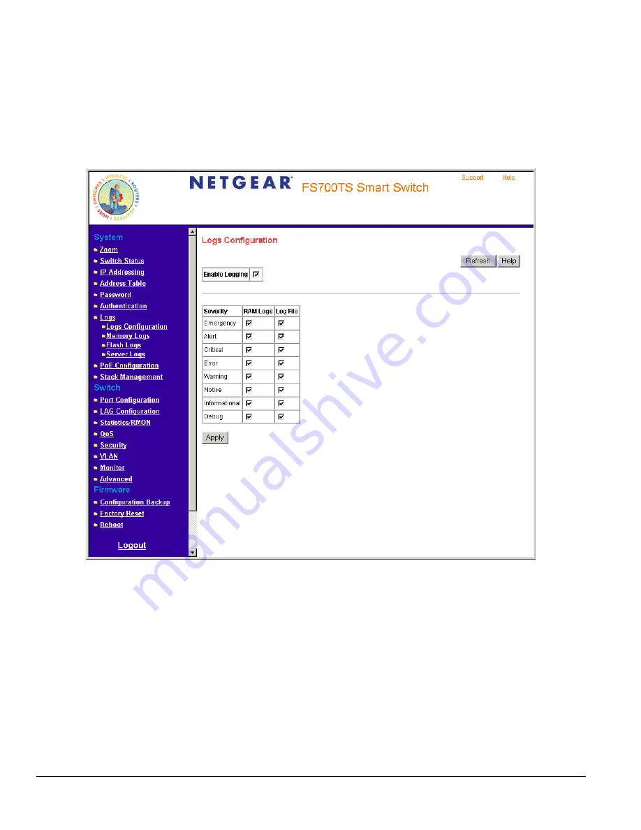
Logs Configuration Page 

contains fields for defining which events are recorded to which logs. It contains fields for enabling logs globally, and 

parameters for defining logs. Log messages are listed from the highest severity to the lowest severity level. When a severity level is selected, all 
severity level choices above the selection are selected automatically.  

To enable event logging: 

1. Click 

Logs >


Logs Configuration

. The 

Logs Configuration Page

 opens.  


Figure 5 - 17: Logs Configuration Page 

The 

Logs Configuration Page

 contains the following fields: 

• 

Enable Logging

 — Indicates if device global logs for Cache, File, and Server Logs are enabled. Console logs are enabled by default. The 

possible field values are:  

– 

Checked — Enables device logs. 

– 

Unchecked — Disables device logs. 

• 

Severity

 — The following are the available log severity levels: 

– 

Emergency — The highest warning level. If the device is down or not functioning properly, an emergency log message is saved to the 
specified logging location. 

– 

Alert — The second highest warning level. An alert log is saved, if there is a serious device malfunction; for example, all device features 
are down. 

– 

Critical — The third highest warning level. A critical log is saved if a critical device malfunction occurs; for example, two device ports are 
not functioning, while the rest of the device ports remain functional. 

Page 46 

Содержание FS728TS - ProSafe Smart Switch

Страница 1: ...pening the NETGEAR Home Page for the FS700TS Series Switch 20 Understanding the Home Page 21 Using The NETGEAR Web Management System Buttons 22 Device Management Buttons 24 Resetting the System 25 Def...

Страница 2: ...Engine ID 87 Defining SNMP Users 88 Defining SNMP Groups 90 Defining SNMP Views 93 Defining SNMP Communities 95 Trap Station Management 99 SNMPv1 2c Notification Recipient 100 SNMPv3 Notification Rec...

Страница 3: ...interface After you power up the switch for the first time you can configure it using the Smart Wizard Discovery Utility or a Web browser Please refer to the screenshots in following pages for the Sma...

Страница 4: ...series switch by plugging in power core 3 Install the Smart Wizard Discovery Utility program on your computer 4 Start the Smart Wizard Discovery utility Section 4 has detailed instructions on the Sma...

Страница 5: ...izard Discovery Web Access Figure 2 2 Web Access Start managing your switch via your web browser The default password is password For a detailed description on web management please refer to Section 5...

Страница 6: ...he Smart Wizard Discovery Utility program on your computer 4 Start the Smart Wizard Discovery utility Section 4 has detailed instructions on the Smart Wizard Discovery Utility 5 Click Discover for the...

Страница 7: ...Figure 2 4 Configuration Setting 7 Choose Disable on DHCP See Figure 2 5 8 Enter your IP address Gateway and Subnet and then type your password and click Set Please make sure your PC and FS700TS serie...

Страница 8: ...Smart Wizard Discovery Configuration Setting Assign Static IP Figure 2 5 Manually Setting IP Address Page 8...

Страница 9: ...Address and Subnet Mask 1 Select your switch by clicking on it Then click on Web Access as highlighted in Figure 2 2 2 Start managing your switch via your web browser The default password is password...

Страница 10: ...Web Management Figure 2 7 Web Management Front Page after Click Web Access on the Smart Wizard Discovery Utility Page 10...

Страница 11: ...lable The upgrade procedure and the required equipment are described in the following section The upgrade procedure is as follows 1 Save the new firmware to your computer 2 Start the Smart Wizard Disc...

Страница 12: ...le name 5 Click Start to download the new firmware file in non volatile memory The system software is automatically loaded to all stacking members Figure 3 3 Enter Password and click Start Note Once t...

Страница 13: ...your CD ROM drive 2 Select the Software folder or click install from Browser auto executed after inserting the Resource CD 3 Run the Setup program to install the Smart Wizard Discovery Utility 4 The I...

Страница 14: ...Figure 4 1 Smart Wizard Discovery Utility Main Screen Page 14...

Страница 15: ...listed switch MAC Address IP Address Protocol Version Product Name System Name Location DHCP Subnet Mask Gateway Figure 4 2 Main Screen Device List Discover By double clicking a listed switch you can...

Страница 16: ...tting Configuration Setting System Name Any desired description for System Name Location Any desired description for Location Password The default password is password DHCP This function is enabled by...

Страница 17: ...o enable new password Main Screen Switch Setting Web Access 8 Select a listed switch from the Device List section Then click Web Access from the Switch Setting see Figure 4 5 9 Enter the default passw...

Страница 18: ...Firmware Upgrade Firmware Path The location of the new firmware If you don t know you can click Browse to locate file Password The default password is password Upgrade State Shows upgrading in progre...

Страница 19: ...stem Defining Device Information Managing Stacking Configuring Device Security Viewing System Logs Configuring Power over Ethernet Configuring Interfaces Defining IP Addresses Defining the Forwarding...

Страница 20: ...for the FS700TS series switch Using the Web Management System Buttons Opening the NETGEAR Home Page for the FS700TS Series Switch The NETGEAR home page for the FS700TS series switch can be accessed f...

Страница 21: ...d the online manual See item 3 in Figure 5 2 Figure 5 2 Home Page Components Navigation Pane The Navigation Pane contains a list of the different features that can be configured including switching fe...

Страница 22: ...ttons in the NETGEAR FS700TS series Switch including the Add Delete Query and Apply Changes buttons Information Buttons The FS700TS Switch web browser contains the following information buttons Table...

Страница 23: ...Page 23...

Страница 24: ...emote locations The FS700TS Switch web browser GUI contains the following management buttons Table 1 2 Device Management Buttons Button Description Applies set changes to the device Adds information t...

Страница 25: ...aved are lost There are two options to reboot Rebooting a particular unit Rebooting the entire stack To open the Reboot Page 1 Click Reboot The Reboot Page opens Figure 5 4 Reboot Page The Reboot Page...

Страница 26: ...s the following topics Viewing the Device Zoom View Viewing the Device Status Viewing the Device Zoom View The System Zoom Page provides a graphic representation of the device including the port and L...

Страница 27: ...n Defines the location where the system is currently running The field may contain is 0 160 characters System Contact Defines the name of the contact person The field may contain is 0 160 characters S...

Страница 28: ...to stacking mode Hardware Version Displays the installed device hardware version number Software Version Displays the installed software version number Boot Version Displays the current boot version...

Страница 29: ...vides an introduction to the user interface and includes the following topics Understanding Stack Topology Stacking Ring Topology Stacking Ports Stacking Members and Unit ID Removing and Replacing Sta...

Страница 30: ...has been manually configured as the Stacking Master the one with the longer up time is elected Stacking Master If the two Master enabled stacking members are the same age Unit 1 is elected Stacking Ma...

Страница 31: ...If the new inserted device has either more than or less ports than the previous device the relevant port configuration is applied to the new stack member If a 24 port switch replaces a 24 port switch...

Страница 32: ...Stack Management The Stack Management Page opens Figure 5 7 Stack Management Page The Stack Management Page contains the following fields Switch Stack Control from Unit 1 to Unit 2 Switches the stack...

Страница 33: ...Switching Between Stack Masters 1 Open the Stack Management Page 2 Check the Switch Stack Control from Unit 1 to Unit 2 check box 3 Click A confirmation message displays Page 33...

Страница 34: ...tication Protocol To define the port authentication properties 1 Click Security Port Authentication Properties The Port Authentication Properties Page opens Figure 5 8 Port Authentication Properties P...

Страница 35: ...bled on the device The possible field values are Enable Enables using a Guest VLAN for unauthorized ports If a Guest VLAN is enabled the unauthorized port automatically joins the VLAN selected in the...

Страница 36: ...ntication The possible field values are Enable Enables immediate port reauthentication This is the default value Disable Disables port reauthentication Reauthentication Period Displays the time span i...

Страница 37: ...econds that lapses before the device re sends a request to the authentication server The field default is 30 seconds Termination Cause Indicates the reason for which the port authentication was termin...

Страница 38: ...that passes before the EAP statistics are refreshed The possible field values are 15 Seconds 30 Seconds 60 Seconds No Refresh Indicates that the EAP statistics are not refreshed Frames Receive Indica...

Страница 39: ...via the port Invalid Frames Receive Indicates the number of unrecognized EAPOL frames that have been received by on this port Length Error Frames Receive Indicates the number of EAPOL frames with an...

Страница 40: ...control is enabled on all ports broadcast only with threshold of 200 kbps Storm Control is enabled by default The Storm Control Page provides fields for configuring broadcast storm control To enable...

Страница 41: ...t Rate Threshold Indicates the maximum rate kilobits per second at which unknown packets are forwarded The range is 70 250 000 The default value is 200 2 Click an interface The Storm Control Modify Pa...

Страница 42: ...system the protection mechanism is invoked It provides the following options for unauthorized packets arriving at a locked port Forwarded Discarded with no trap Discarded with a trap Shuts down the p...

Страница 43: ...ates the action to be applied to packets arriving on a locked port The possible field values are Forward Forwards packets from an unknown source without learning the MAC address Discard Discards packe...

Страница 44: ...pens Figure 5 16 Password Page The Password Page contains the following fields Old Password Indicates the current password used to access the system New Password Defines a new password for accessing t...

Страница 45: ...ctioning Alert 1 Indicates that the system needs immediate attention Critical 2 Indicates that the system is in a critical state Error 3 Indicates that a system error has occurred Warning 4 Indicates...

Страница 46: ...ing Indicates if device global logs for Cache File and Server Logs are enabled Console logs are enabled by default The possible field values are Checked Enables device logs Unchecked Disables device l...

Страница 47: ...formation Informational Provides device information Debug Provides debugging messages RAM Logs Defines the minimum severity level from which logs are sent to the RAM Log kept in RAM Cache Log File Def...

Страница 48: ...gs Click Logs Memory Logs The Memory Logs Page opens Figure 5 18 Memory Logs Page The Memory Logs Page contains the following fields ID Displays the table entry number Log Index Displays the log numbe...

Страница 49: ...The message log is available after reboot To view the message logs Click Logs Flash Logs The Flash Logs Page opens Figure 5 19 Flash Logs Page The Flash Logs Page contains the following fields ID Disp...

Страница 50: ...system logs are sent to the remote server Only one facility can be assigned to a single server If a second facility level is assigned the first facility is overridden All applications defined for a d...

Страница 51: ...Unchecked Maintains the remote servers 2 Click The Add Remote Logs Page opens Figure 5 21 Add Remote Logs Page 3 Define the fields 4 Click The log is defined and the device is updated Page 51...

Страница 52: ...on for the FS752TPS The PoE Configuration Page contains system PoE information for enabling PoE on the device monitoring the current power usage and enabling PoE traps To enable PoE on the device 1 C...

Страница 53: ...his is the highest PoE priority level Class Indicates the amount of power assigned to the powered device connected to the selected interface The powered device classifies devices and the devices use t...

Страница 54: ...rrences Denied Counter Indicates times the powered device was denied power Absent Counter Indicates the times the powered device did not receive power from the power supply because the powered device...

Страница 55: ...onfiguration Page contains the following fields Unit No Indicates the stacking number or LAG number Interface Displays the port number Port Description Provides a user defined device description Link...

Страница 56: ...mode on the Port Back Pressure mode is used with half duplex mode to disable ports from receiving messages Back Pressure mode is enabled by default Flow Control Displays the flow control status on th...

Страница 57: ...ides link redundancy Ports added to a LAG lose their individual port configuration When ports are removed from the LAG the original port configuration is applied to the ports Ensure the following when...

Страница 58: ...6 LAG Settings Page The LAG Settings Page contains the following fields Interface Displays the LAG number LAG Description Displays the user defined port name Link Status Displays the link operational...

Страница 59: ...ing Auto negation of Flow Control FC is enabled by default Admin Advertisement Defines the auto negotiation setting the port advertises The possible field values are Max Capability Indicates that all...

Страница 60: ...to LAGs 1 Click LAG Configuration LAG Membership The LAG Membership Page opens Figure 5 28 LAG Membership Page The LAG Membership Page contains the following fields LAG Port Displays the LAG number L...

Страница 61: ...2 Click a LAG The Modify LAG Membership Page opens Figure 5 29 Modify LAG Membership Page 3 Select a port to attach to the selected LAG 4 Click The LAG is defined and the device is updated Page 61...

Страница 62: ...VLANs Layer 3 routers identify segments and coordinate with VLANs VLANs are Broadcast and Multicast domains Broadcast and Multicast traffic is transmitted only in the VLAN in which the traffic is gene...

Страница 63: ...tes whether unauthorized users can access a Guest VLAN The possible field values are Enable Enables unauthorized users to use the Guest VLAN Disable Disables unauthorized users from using the Guest VL...

Страница 64: ...isplays the user defined VLAN ID VLAN Name Displays the name of the VLAN VLAN Type Indicates the VLAN type The possible field values are Static Indicates the VLAN is user defined Default Indicates the...

Страница 65: ...mber 1 is the default VLAN and cannot be deleted from the system To open the Interface PVID Settings Page 1 Click Switch VLAN Interface PVID Settings The Interface PVID Settings Page opens Figure 5 33...

Страница 66: ...2 Define the fields 3 Click The PVID settings are saved and the device is updated Page 66...

Страница 67: ...n have a different IP address every time the device connects to the network Note the following when configuring IP Addresses If the device was accessed using the Smart Wizard Discovery Utility the IP...

Страница 68: ...f its neighbors is known To define ARP information 1 Click IP Addressing ARP The ARP Page opens Figure 5 35 ARP Page The ARP Page contains the following fields ARP Entry Age Out Specifies the amount o...

Страница 69: ...dynamically Static Indicates the ARP entry is a static entry Delete Removes a specific ARP entry The possible field values are Checked Removes the selected ARP entries Unchecked Maintains the current...

Страница 70: ...ble from overflowing a dynamic MAC address from which no traffic arrives for a set period is erased The Defining the Forwarding Address Tables Page contains parameters for defining the age interval on...

Страница 71: ...y The possible field values are Checked Removes the selected entry Unchecked Maintains the current static forwarding database To prevent static MAC addresses from being deleted when the device is rese...

Страница 72: ...s the following fields Address Aging Specifies the amount of time the MAC address remains in the Dynamic MAC Address table before it is timed out if no traffic from the source is detected The default...

Страница 73: ...e 1 Click Address Table Dynamic Addresses The Dynamic Addresses Page opens 2 Select a port MAC Address and VLAN ID 3 Select an Address Table Sort Key 4 Click The Dynamic MAC Address Table is queried a...

Страница 74: ...ed network can cause bridges to forward traffic indefinitely resulting in increased traffic and reducing network efficiency To configure STP on the device 1 Click Advanced Setup Spanning Tree The Span...

Страница 75: ...tes that STP is currently disabled on the port The port forwards traffic while learning MAC addresses Blocking Indicates that the port is currently blocked and cannot forward traffic or learn MAC addr...

Страница 76: ...STP on the port Disable Disables STP on the port This is the default value Fast Link Indicates if Fast Link is enabled on the port If Fast Link mode is enabled for a port the Port State is automatical...

Страница 77: ...more connections connected to a shared segment Disabled The port is not participating in the Spanning Tree Speed Indicates the speed at which the port is operating Path Cost Indicates the port contrib...

Страница 78: ...y one of the following methods Strict Priority Ensures that time sensitive applications are always forwarded Strict Priority SP allows the prioritization of mission critical time sensitive traffic ove...

Страница 79: ...settings can be reassigned to the interface in the CoS Page To enable QoS 1 Click QoS General CoS The CoS Page opens Figure 5 42 CoS Page The CoS Page contains the following Unit No Displays the stack...

Страница 80: ...assifies traffic based on the DSCP tag value None Indicates that Trust is not enabled on the device Interface Displays the interface for which the global QoS parameters are defined Port Selects the po...

Страница 81: ...Page opens Figure 5 43 Queue Page The Queue Page contains the following fields Strict Priority Specifies whether traffic scheduling is based strictly on the queue priority WRR Assigns WRR weights to...

Страница 82: ...er queue and or per interface Shaping is determined by the lower specified value The queue shaping type is selected in the Bandwidth Page To define bandwidth settings 1 Click QoS General Bandwidth The...

Страница 83: ...fines the CIR in megabytes per seconds The possible field range is 0 07 256 Ingress Rate Limit Status Determines the ingress port bandwidth settings for the selected interface range is 62 1000000 Kbps...

Страница 84: ...s Class of Service Specifies the CoS priority tag values where zero is the lowest and 7 is the highest Queue Defines the traffic forwarding queue to which the CoS priority is mapped Eight traffic prio...

Страница 85: ...o Queue The DSCP to Queue Page opens Figure 5 47 DSCP to Queue Page The DSCP to Queue Page contains the following fields DSCP In Displays the incoming packet s DSCP value Queue Specifies the traffic f...

Страница 86: ...vacy Protects against the disclosure of message content Cipher Block Chaining CBC is used for encryption Either authentication is enabled on an SNMP message or both authentication and privacy are enab...

Страница 87: ...Displays the local device Engine ID The field value is a hexadecimal string Each byte in hexadecimal character strings is two hexadecimal digits Each digit can be separated by a period or a colon The...

Страница 88: ...anced SNMP Users The SNMP Users Page opens Figure 5 49 SNMP Users Page The SNMP Users Page contains the following fields ID Displays the table entry number User Name Contains a list of user defined us...

Страница 89: ...MD5 Password The HMAC MD5 96 password is used for authentication The user should enter a password SHA Password Users are authenticated using the HMAC SHA 96 authentication level The user should enter...

Страница 90: ...roups Page contains the following fields ID Indicates the stacking number Group Name Displays the user defined group to which access control rules are applied The field range is up to 30 characters Se...

Страница 91: ...are Read Management access is restricted to read only Changes cannot be made to the assigned SNMP view Write Management access is read write Changes can be made to the assigned SNMP view Notify Sends...

Страница 92: ...nced SNMP Groups The Groups Page opens 2 Click the ID of the group you want to modify The Modify Groups Page opens Figure 5 53 Modify Groups Page 3 Modify the fields 4 Click The SNMP group profile is...

Страница 93: ...e Views Page opens Figure 5 54 Views Page The Views Page contains the following fields View Name Displays the user defined views The view name can contain a maximum of 30 alphanumeric characters ID In...

Страница 94: ...2 Click The Add Views Page opens Figure 5 55 Add Views Page 3 Define the fields 4 Click The view is defined and the device is updated Page 94...

Страница 95: ...Page The Communities Page is divided into the following tables Basic Table Advanced Table SNMP Communities Basic Table The SNMP Communities Basic Table contains the following fields when using SNMPv1...

Страница 96: ...selected SNMP community Unchecked Maintains the SNMP communities SNMP Communities Advanced Table The SNMP Communities Advanced Table contains the following fields ID Indicates the table entry number M...

Страница 97: ...anagement Station Community String and Basic or Advanced tables 4 Click The SNMP community is added and the device is updated To modify SNMP community settings 1 Click Advanced SNMP Communities The Co...

Страница 98: ...Figure 5 58 Modify Communities Page 3 Modify the SNMP Management Station Community String and Basic or Advanced tables 4 Click The SNMP community is modified and the device is updated Page 98...

Страница 99: ...ervices Identifying Management Trap Targets Trap Filtering Selecting Trap Generation Parameters Providing Access Control Checks To define trap station management 1 Click Advanced SNMP Trap Station Man...

Страница 100: ...d Maintains the list of recipients SNMPv3 Notification Recipient The SNMPv3 Notification Recipient table contains the following fields ID Indicates the stacking number Recipient IP Displays the IP add...

Страница 101: ...ent Page 3 Define the Recipient IP Notification Type Community String Notification Version User Name UPD Port Filter Name Timeout and Retries fields 4 Click The SNMP Notification recipients are define...

Страница 102: ...ce can send SNMP notifications The possible field values are Enable Enables SNMP notifications Disable Disables SNMP notifications Authentication Notifications Specifies whether SNMP authentication fa...

Страница 103: ...age contains the following fields Filter Name Contains a list of user defined notification filters ID Indicates the Trap Filter Settings Table entry number Object Identifier Subtree Displays the OID f...

Страница 104: ...he list of filters 2 Click The Add Trap Filter Settings Page opens Figure 5 63 Add Trap Filter Settings Page 3 Define the Filter Name New Object Identifier Tree and Filter Type fields 4 Click The SNMP...

Страница 105: ...ge contains the following fields Backup Current setting to file Backs up the current System settings to file Restore Saved Setting From File Changes the current system file to a previously saved file...

Страница 106: ...Figure 5 65 Configuration Download Page Page 106...

Страница 107: ...ebugging feature Port mirroring also enables switch performance monitoring Network administrators can configure port mirroring by selecting a specific port from which to copy all packets and other por...

Страница 108: ...d The possible field values are Active Indicates the port is currently monitored Ready Indicates the port is not currently monitored Delete Removes the port mirroring session The possible field values...

Страница 109: ...ort Mirroring The Add Port Mirroring Page opens 2 Click an interface The Modify Port Mirroring Page opens Figure 5 68 Modify Port Mirroring Page 3 Modify the Type field 4 Click The port mirroring sett...

Страница 110: ...e Approximated Cable Length test To test cables 1 Click Monitor Copper Cable The Copper Cable Page opens Figure 5 69 Copper Cable Page The Copper Cable Page contains the following fields Unit No Indic...

Страница 111: ...icates the last time the port was tested Cable Length Indicates the approximate cable length This test can only be performed when the port is up and operating at 1 Gbps 2 Click The test results are di...

Страница 112: ...ic cable tests are displayed Port Displays the port IP address on which the cable is tested Temperature Displays the temperature C at which the cable is operating Voltage Displays the voltage at which...

Страница 113: ...errors that occurred on the device To view RMON statistics 1 Click Statistics RMON RMON Statistics The RMON Statistics Page opens Figure 5 71 RMON Statistics Page The RMON Statistics Page contains th...

Страница 114: ...n the interface since the device was last refreshed Undersize Packets Displays the number of undersized packets less than 64 octets received on the interface since the device was last refreshed Oversi...

Страница 115: ...l Page The History Control Page contains the following fields History Entry No Displays the entry number for the History Control Table page Source Interface Displays the interface from which the histo...

Страница 116: ...ory entry number The Add History Control opens Figure 5 73 Add History Control Page 3 Define the Source Interface Owner Sampling Interval Max No of Samples to Keep and Samples intervals fields 4 Click...

Страница 117: ...ets Displays the number of packets received on the interface since the device was last refreshed including bad packets Multicast and Broadcast packets Broadcast Packets Displays the number of good Bro...

Страница 118: ...e bits but includes FCS octets that had either a bad Frame Check Sequence FCS with an integral number of octets FCS Error or a bad FCS with a non integral octet Alignment Error number The field range...

Страница 119: ...ontrol The Events Control Page opens Figure 5 75 Events Control Page The Events Control Page contains the following fields ID Indicates the stacking number Event Entry Displays the event Community Dis...

Страница 120: ...Indicates that no event occurred Time Displays the time that the event occurred Owner Displays the device or user that defined the event Delete Removes a RMON event The possible field values are Chec...

Страница 121: ...Event Logs The Events Logs Page opens Figure 5 76 Events Logs Page The Events Logs Page contains the following fields ID Indicates the Events Logs Page table entry Event Displays the RMON Events Log N...

Страница 122: ...ariable Interface Displays interface for which RMON statistics are displayed The possible field values are Port Displays the RMON statistics for the selected port LAG Displays the RMON statistics for...

Страница 123: ...th the Log and Trap mechanism are used to report alarms Falling Threshold Displays the falling counter value that triggers the falling threshold alarm The falling threshold is graphically presented on...

Страница 124: ...iguration file The stacking defaults are not restored from this page including The stacking mode The stacking cables The Unit ID numbering To restore stacking defaults press the button on the front pa...

Страница 125: ...sing the Factory Reset function from a Web browser Table A 1 Default Settings Feature FS700TS Default Setting Port Speed Auto negotiation Port Duplex Auto negotiation Flow Control half duplex Enabled...

Отзывы: