background image

46

NetApp AltaVault Cloud Integrated Storage Installation and Service Guide for Physical Appliances


Beta Draft

System components

Using LEDs to check the status of the system

2.

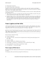
Use the following table to understand the system LEDs:

3.

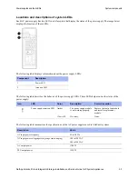
Use the following table to understand the AltaVault appliance system components on the chassis front:

Component

Description

1

System LEDs

When the bezel is in place, the LEDs are arranged horizontally in the following left-to-right order:

• Power

• Fault (System Attention LED)

• Controller A activity (controller installed in the top bay only with no secondary controller)

Note: 

When the bezel is removed, the system LEDs on the chassis are arranged in the same order as on 

the bezel, but in a top-to-bottom vertical orientation.

Component 

Description

Bezel

The bezel covers the front of the AltaVault system chassis. From the bottom of the front 
bezel, you can see four system LEDs (arranged horizontally) that indicate the status of the 

system.

Fan modules

There are six redundant and hot-swappable fan modules installed in slots A1 through A3 and 
B1 through B3. 

The bottom row contains a blank.

You have to remove the front bezel to see the fan modules. The Attention LED is set to 
Amber if the fan module is not working properly.

System LEDs

The chassis has four LEDs (arranged vertically) that indicate the status of the system:

• Power

• Attention

• Activity A (Controller)

• Activity B (unused in AltaVault)

These LEDs are located behind the bezel. Remove the front bezel to see these LEDs.

The system LEDs and the LEDs visible when the bezel is installed are the same, except that 
the bezel LEDs are aligned horizontally and the system LEDs are aligned vertically. Both 

sets of LEDs provide the same information about the system.

Chassis handles

The chassis has two handles on each side that assist with lifting the system. The handles are 
integrated into the chassis and fold flush when not in use.

Содержание AltaVault Cloud Integrated Storage 4.1

Страница 1: ... and Service Guide for Physical Appliances NetApp Inc 495 East Java Drive Sunnyvale CA 94089 U S Telephone 1 408 822 6000 Fax 1 408 822 4501 Support telephone 1 888 463 8277 Web www netapp com Feedback doccomments netapp com Part number 215 10477_B0 June 2017 ...

Страница 2: ......

Страница 3: ...sis in four post racks 14 Important considerations for successful installations 14 Installing an AltaVault controller chassis in a four post rack 15 Installing disk shelves and disk drives 18 Installing additional preconfigured disk drives on a shelf 18 Chapter 3 Connecting the system 19 Connecting the controller and the shelves 19 Supported cable configurations 22 Networking options for ports 22 ...

Страница 4: ... 56 Internal FRUs 58 Appendix C System maintenance 59 Migrating data from a SteelStore appliance to an AltaVault appliance 60 Shutting down controllers 60 Replacing controllers 60 Shutting down and removing the controller from the chassis 61 Moving working FRUs from the controller 62 Reinstalling and connecting the controller in the chassis 63 Installing a controller in a chassis 64 Replacing a co...

Страница 5: ...placing the RTC clock coin battery 83 Removing an RTC battery 83 Installing an RTC battery 84 Disposing of batteries 85 Replacing a faulty hard disk drive on an AltaVault AVA400 or AVA800 appliance 86 Replacing disk shelf power supplies and other FRUs 86 Returning failed parts 86 Disposing of batteries 86 Copyright information 87 Trademark information 89 How to send your comments 91 Index 93 ...

Страница 6: ...6 NetApp AltaVault Cloud Integrated Storage Installation and Service Guide for Physical Appliances Contents ...

Страница 7: ...ovides a list of prerequisites for successfully installing the NetApp AltaVault appliance It includes the following sections Workflow diagram on page 8 Site clearance requirements on page 8 Environmental site system requirements on page 9 Controller electrical requirements on page 9 Configuration worksheet on page 9 Obtaining documentation and release notes on page 10 ...

Страница 8: ...nance of a AltaVault system Clearance requirements Location Value Airflow and cooling System front System rear 6 inches 15 2 cm 12 inches 30 5 cm Maintenance System front System rear 30 inches 76 2 cm 36 inches 91 4 cm M o u n t th e c o n tro lle r c h a s s is o n th e ra c k B e c o m e fa m ilia r w ith s y s te m c o m p o n e n ts In s ta ll th e d is k s h e lv e s o n th e ra c k P re p a ...

Страница 9: ... with two functioning power supplies Configuration worksheet Use the configuration worksheet to note any information that you require for the AltaVault deployment including Appliance information on page 39 Cloud provider credentials and storage configuration on page 39 Network connectivity on page 40 Advance features on page 41 Environmental tolerances Normal operating range Operating temperature ...

Страница 10: ... documentation set includes the following NetApp AltaVault Cloud Integrated Storage Installation and Service Guide for Physical Appliances SAS Disk Shelves Installation and Service Guide for DS4243 DS2246 DS4486 and DS4246 NetApp AltaVault Cloud Integrated Storage Installation and Service Guide for Virtual Appliances NetApp AltaVault Cloud Integrated Storage Installation and Service Guide for Clou...

Страница 11: ...ystems and disk shelves install them from the bottom to the top of the rack for the best stability For consistency with AltaVault system stacking and for stability position the controller above the storage stack as the storage stack is heavier than the controller Caution If you are installing the controller chassis without using the mechanical lift at least three people must be available to lift t...

Страница 12: ...r mounting the two piece telco tray and mid mount brackets to the rack 16 M5 0 8 x 20 Pilot screws 16 M6 1 x 20 Pilot screws 16 10 32 x 75 Pilot screws 16 12 24 x 75 Pilot screws Note You do not need to use all the screws listed Use the appropriate size screws that match the threading of the holes in your rack Installing an AltaVault controller chassis in a two post rack Use the instructions that ...

Страница 13: ...ble 6 For the right half of the telco tray installation repeat Step 3 and Step 4 7 Choose either a manual or lift installation If you are installing the controller chassis using a lift do the following For installing the controller chassis in a mid mount position Align the screw holes on one side of the controller chassis with the screw holes on the mid mounting bracket Secure the bracket to the c...

Страница 14: ...s of controller chassis in four post racks Use the four post rail kit that ships with the controller to mount the controller chassis in a four post rack NetApp recommends that you use the NetApp equipment rails in this application to be consistent with how AltaVault systems are treated If you are installing multiple AltaVault systems and disk shelves you should install them from the bottom to the ...

Страница 15: ...on NetApp recommends using the NetApp kit for non NetApp four post racks that includes the following One set of left side rails and one set of right side rails for four post mounting Bagged screws in the following sizes 16 M5 0 8 x 20 Pilot screws 16 M6 1 x 20 Pilot screws 16 10 32 x 75 Pilot screws 16 12 24 x 75 Pilot screws Bagged clip nuts in the following sizes 16 10 32 clip nuts 16 12 24 clip...

Страница 16: ...wo on the rear side of each rail except for NetApp cabinets where a single screw is used per rail 5 Locate the position the rail will occupy when installed on the right rear of the four post rack Note When possible install the equipment from the bottom of the rack up so that you can use the equipment underneath as a guide for installing the next set of rails Place controllers in the rack no higher...

Страница 17: ...llustrates the process of installing the rails in a four post rack 11 If you are installing the controller chassis using a lift go to Step 12 If you are installing the controller chassis manually at least three people must be available to lift the controller chassis 12 Lift the controller chassis using the chassis handles and slide it onto the rail assemblies 13 Use screws of the appropriate size ...

Страница 18: ...ed 12 pack of disk drives into the shelf If you are installing two sets of 12 pack disk drives install the entire 12 pack disk drives in either in the top half of the rack which are slots 0 11 or the bottom half of the rack which are slots 12 23 Do not mix up the disks of a disk pack between the top and bottom halves of the rack as they are preconfigured as a group To install a new set of preconfi...

Страница 19: ... page 29 Connecting the controller and the shelves You can connect the AltaVault AVA400 to up to three shelves and the AVA800 model can connect to up to four shelves The AltaVault controller and AVA10S disk shelves connect using a cable that contains a Mini SAS cable connector on one end below and a QSFP cable connector on the other end Each connector connects a Mini SAS cable connector to a Mini ...

Страница 20: ...le connector and connects to a QSFP port on the rear of the disk shelf The following table displays AltaVault components and descriptions Altavault systems support controller to shelf cables with mini SAS QSFP connectors in 1 2 and 3 meter lengths Shelf to shelf cables QSFP QSFP connectors are supported in 0 5 1 2 3 and 5 meter lengths Component Description 1 Mini SAS cable connector 2 Latch relea...

Страница 21: ...Connectingthesystem The image below displays the rear view of an AltaVault controller The RAID controllers are located in slots 1 and 3 and contain the mini SAS HD ports used to connect the mini SAS connector end of a cable The image below displays the QSFP ports on the rear of the disk shelf used to connect the QSFP connector end of a cable ...

Страница 22: ...ng options for ports Port Label Function Type Description NetApp Marketing Part Number Notes e0a e0b e0c e0d 10GbE Copper Passive Cable Cisco Twinax 10 GbE Copper SFP 1m Cable Cisco Twinax 10 GbE Copper SFP 3m Cable Cisco Twinax 10 GbE Copper SFP 5m X SFP H10GB CU1M R6 X SFP H10GB CU3M R6 X SFP H10GB CU5M R6 Optical Cable OM3 LC to LC cable 2m Cable OM3 LC to LC cable 5m Cable OM3 LC to LC cable 1...

Страница 23: ...oller and the shelves Connectingthesystem Supported cable configuration for an AltaVault controller and one shelf The following diagram displays the supported cable configuration for one AltaVault controller AVA400 or AVA800 and one AVA10S shelf Cabling diagram for an AltaVault controller and one shelf Controller Shelf 1 ...

Страница 24: ...ctingthe controllerandthe shelves Supported cable configuration for an AltaVault controller and two shelves The following diagram displays the supported cable configuration for one AltaVault controller AVA400 or AVA800 and two AVA10S shelves Controller Shelf 2 Shelf 1 Cabling diagram for an AltaVault controller and two shelves ...

Страница 25: ...shelves Connectingthesystem Supported cable configuration for an AltaVault controller and three shelves The following diagram displays the supported cable configuration for one AltaVault controller AVA400 or AVA800 and three AVA10S shelves Controller Shelf 3 Shelf 2 Cabling diagram for an AltaVault controller and three shelves Shelf 1 ...

Страница 26: ...ngthe controllerandthe shelves Supported cable configuration for an AltaVault controller and four shelves The following diagram displays the supported cable configuration for one AltaVault controller AVA800 and four AVA10S shelves Controller Shelf 4 Shelf 3 Cabling diagram for the AVA800 controller and four shelves Shelf 2 Shelf 1 ...

Страница 27: ...onnect the AltaVault controller to the disk shelf 1 Choose one of the supported cable configuration diagrams to follow for your deployment Supported cable configuration for an AltaVault controller and one shelf on page 23 Supported cable configuration for an AltaVault controller and two shelves on page 24 Supported cable configuration for an AltaVault controller and three shelves on page 25 Suppor...

Страница 28: ...bling diagram selected for your deployment repeat the steps for each cable connection until all of the supported cable connections for the selected configuration are complete Connecting the controller to the networks Connect the management port wrench icon on your controller to the Ethernet switch in your management network using a network cable See your network administrator for help connecting t...

Страница 29: ...power source is in the off O position The information contained in this section assumes each chassis is connected directly to the building mains If you are installing a chassis in a 4 post rack the power is delivered through power distribution units PDUs that use C13 C14 jumper cords in most cases The input cord from each PDU connects to the mains Each chassis should be connected to separate PDUs ...

Страница 30: ...id shelf ID for an AltaVault system could be one of 00 01 10 or 11 The default shelf ID is 00 4 If a change to a shelf ID is required perform the following steps a Using one hand hold the left ear cover between your thumb and index finger b Pull either the top or the bottom of the cover until one end is released then pull off the left ear cover as displayed below c Press and hold the shelf ID butt...

Страница 31: ... takes effect h Replace the left ear cover 5 Power on the controller by flipping the power switches to the on position to power on the controller 6 If the bezel was removed during installation place it back on the appliance to complete the hardware installation 7 When the AltaVault virtual appliance starts the login prompt appears Log in to the AltaVault appliance by opening a connection using a t...

Страница 32: ...32 NetApp AltaVault Cloud Integrated Storage Installation and Service Guide for Physical Appliances Connecting the system Connecting the power and starting the system ...

Страница 33: ...Before you begin ensure that you have serial console access to the AltaVault appliance For more information refer to Connecting the controller to a computer on page 28 The configuration wizard automatically starts when you log in to the AltaVault appliance for the first time When the login prompt displays log in using the default login admin and default password password You can now configure the ...

Страница 34: ... steps For more information see Running the AltaVault appliance CLI configuration wizard on page 33 2 Enter configuration mode and set the Service Processor password in the controller using the following CLI commands Step 3 Use DHCP on the primary interface You are given the option to enable the DHCP to automatically assign an IP address to the primary interface for the AltaVault appliance For Alt...

Страница 35: ...rvice Processor after the SP is configured with an IP address and password Before you begin Ensure that you have serial console access to the AltaVault appliance For more information refer to Connecting the controller to a computer on page 28 Set the SP password as described in Setting the Service Processor password on page 34 Provide an IP address for the SP if not using DHCP that is on the same ...

Страница 36: ...rnal switch Would you like to configure the SP y n y Would you like to enable DHCP on the SP LAN interface y n n Please enter the IP address for the SP unknown 172 16 100 4 Please enter the netmask for the SP unknown 255 255 255 0 Please enter the IP address for the SP gateway unknown 172 16 100 1 Do you want to enable IPv6 on the SP y n n Output sample Service Processor New Network Configuration ...

Страница 37: ...s Sample output truncated Next steps After you log in to AltaVault appliance the configuration wizard displays and allows you to choose from the following Specify system settings including time zone and DNS Configure cloud settings including cloud credentials licenses and data encryption Configure data interfaces that are used to receive data from the backup application Configure CIFS shares or NF...

Страница 38: ...38 NetApp AltaVault Cloud Integrated Storage Installation and Service Guide for Physical Appliances Deploying AltaVault Nextsteps ...

Страница 39: ...d to configure and enable email notifications 1 7 Email address or alias for Notification of Events and Failures There are two groups of notifications Events Group and Failure Group 1 8 Domain name for the appliance This needs to be configured in DNS as well to resolve fqdn of the appliance 1 9 Time zone in which the appliance will be installed 2 Cloud provider credentials and storage configuratio...

Страница 40: ...e AD Domain and the Domain controller must be listed in the _LDAP section in the Primary DNS 2 12 Username s Groups to be given access to the share 2 13 NFS Export Name naming convention to be used 2 14 Is NFSv4 Kerberos required If yes Kerberos keytab and conf files are required 3 Network connectivity Notes 3 1 Number of 1gbE 10GbE Data Interfaces to be used 3 2 Specify speed of Data Backup LAN 1...

Страница 41: ... and Service Guide for Physical Appliances 41 Beta Draft Configuration worksheet Administrator s configuration worksheet 4 Advance features Notes 4 1 Bandwidth throttling for replication to cloud 4 2 Alarms Announcements Logging Scheduled Reports 4 3 SNMP ...

Страница 42: ...42 NetApp AltaVault Cloud Integrated Storage Installation and Service Guide for Physical Appliances Beta Draft Administrator s configuration worksheet Configuration worksheet ...

Страница 43: ... LEDs on page 54 Controller components and their LEDs on page 54 AltaVault appliance components The AltaVault AVA400 or AVA800 chassis contains the following components AVA400 or AVA800 controller Front panel with Power Warning and controller Activity LEDs Two field replaceable 1300W 100 240V AC auto ranging plug in power supply units Three field replaceable high speed fan modules Rack mounting ki...

Страница 44: ...system chassis Supported expansion shelf models You can use the following table to determine the possible AltaVault appliance and expansion shelf combinations Description Controller Rack units 6 U Height 10 2 in 25 9 cm Width Without mounting flanges 17 6 in 44 68 cm With mounting flanges 19 in 48 26 cm Depth 24 3 in 61 72 cm Weight 105 lbs 47 6 kg AltaVault appliance Expansion shelves AVA10S RAID...

Страница 45: ...y You must shut down the system add the drives and restart the system The two power supplies on an AltaVault expansion shelf are field replaceable units FRUs The power supplies have fans The PSU fans are for PSU cooling and maintaining chassis thermals The fans continue to run even if the power supply unit PSU itself fails If the PSU fails do not remove it from the chassis until a replacement is i...

Страница 46: ...tom of the front bezel you can see four system LEDs arranged horizontally that indicate the status of the system Fan modules There are six redundant and hot swappable fan modules installed in slots A1 through A3 and B1 through B3 The bottom row contains a blank You have to remove the front bezel to see the fan modules The Attention LED is set to Amber if the fan module is not working properly Syst...

Страница 47: ...U is delivering power to the system Fault System Attention LED Amber Clear off The system is shut down or a fault occurred in the chassis The error might be in a PSU fan or controller The LED also is lit when there is an internal FRU failure or the system is in maintenance mode Note You can check the fault LED on the back of each controller to see where the problem occurred The system is operating...

Страница 48: ... Ports Link LED Activity LED Displays green when the port is linked and displays white when there is no link Displays orange when the port is active and displays white when there is no activity PCM PCM Attention LED is used on the AltaVault controller for debugging purposes GbE and management ports Link LED Activity LED Displays green when the port is linked and displays white when there is no lin...

Страница 49: ...are not hot swappable Boot media device RAID controller assemblies Real Time Clock RTC coin battery System DIMM Slot numbering and associated components An AltaVault controller controls three fan modules Controller A controls the fans in slots A1 through A3 If a controller is removed from the chassis the fans in all three associated fan modules stop spinning Three fan modules are shipped preinstal...

Страница 50: ...e release latch and an attention LED that indicates the status of the fan module The image below displays the fan module component locations The following table displays the fan module components and descriptions Chassis rear A B One controller module in this slot AltaVault systems support only one controller module in the chassis A blank is installed over slot B 1 2 An AC power supply is located ...

Страница 51: ... to minimize disruption to the system s airflow If the fan module is not replaced within two minutes the system shuts down to avoid overheating For information on replacing fan modules see Hot swapping controller fan modules on page 67 Fan redundancy policy The AltaVault system fan redundancy policy enables the system to continue operating with a single fan failure one fan failure in any one fan m...

Страница 52: ...utes of the Alarm event email The alarm can be checked on the UI Reports Alarms Status Power supplies and their LEDs AltaVault systems ship with two AC power supplies preinstalled in the chassis in the slots labeled 1 and 2 The AC power supplies are installed on the rear of the chassis The power supplies are fully redundant hot swappable field replaceable units FRUs The system remains operational ...

Страница 53: ...ibes the behavior of the power supply LEDs These LEDs help monitor the status of the power supply The following table summarizes the specifications of the AC power supplies used in AltaVault systems Component Description 1 Power LED 2 Attention LED Icon LED Color Description Corrective action Power supply attention LED Amber Clear off The power supply module is not working properly No errors Remov...

Страница 54: ...controller contains the following Components for removing and installing controller Ports and LEDs on the AltaVault controller Internal FRUs and their LEDs Use the components in this table to help remove or install a controller in a chassis Controller LED behaviors The LEDs on the face plate of the controller display the status of its network or disk shelf connections and identifies the controller...

Страница 55: ... the controller ports and LEDs on the left side of the controller faceplate The following table describes ports and LEDs on the left side of the controller Component Description 1 SAS port LEDs not used 2 SAS port not used 3 10 GbE port LEDs 4 10 GbE Ports 5 CNA port LEDS not used 6 CNA ports not used 7 NVRAM LED not used Note The NVRAM is physically present but not used in the AltaVault software ...

Страница 56: ... controller has four 10Gb Ethernet 10GbE ports identified with labels e0a e0b e0c and e0d LNK Green Amber flashing Off A link is established between the port and some upstream device Traffic is flowing over the connection No traffic is flowing over the connection Controller attention LED Amber Off A problem has occurred in the controller This in turn has caused the system attention LED on the chas...

Страница 57: ...e port and some upstream device No link is established Traffic is flowing over the connection No traffic is flowing over the connection and Remote management The remote management port is labeled with a wrench symbol It is identified as primary e0M in the CLI commands and output This port is used for managing the AltaVault system LNK Left LED Activity Right LED Green Off Amber flashing Off A link ...

Страница 58: ...oot device The boot device stores a primary and secondary set of system files also called the boot image that the system uses when it boots The attention LED is next to the boot device on the motherboard Not applicable System DIMM Each AltaVault controller has eight 32G DIMMs All eight DIMMs must be installed for the system to be fully functional Not applicable RAID Controller assemblies The RAID ...

Страница 59: ...ontroller fan modules on page 67 Hot swapping controller power supplies on page 70 Adding an additional RAID group to a configured appliance on page 73 Replacing internal FRUs on page 74 Replacing a boot device in a controller on page 75 Replacing system DIMMs on page 79 Replacing RAID controllers on page 83 Replacing the RTC clock coin battery on page 83 Replacing disk shelf power supplies and ot...

Страница 60: ...eplacing the controller itself shut down the controller A clean shutdown of the AltaVault controller ensures that all data has been written to the storage subsystems You must also disconnect power from the power supplies before these replacement procedures To shut down a stand alone AltaVault controller 1 To shut down the AltaVault controller enter the following CLI command CLI reload halt When th...

Страница 61: ...ole NetApp recommends that you export your configuration and store it in a secure location as a preventative measure against unexpected failures Replacing an AltaVault controller includes the following processes Shutting down and removing the controller from the chassis on page 61 Moving working FRUs from the controller on page 62 Reinstalling and connecting the controller in the chassis on page 6...

Страница 62: ...ved you should minimize the handling of the components by installing them in the replacement controller as soon as they are removed from the impaired controller Then install the replacement controller module in the system chassis To move all the working FRUs from the impaired controller to the new controller module 1 Place the replacement controller module next to the impaired module and open the ...

Страница 63: ...roller in the same configuration as the source controller 4 Restart the target AltaVault appliance After swapping the disks when you restart the target AltaVault appliance the following message displays The secure vault fails to unlock This is because of the serial number mismatch between the appliances You cannot use the data store because you cannot access the data store encryption key in the se...

Страница 64: ...ention LED on the chassis rear are not lit after the system has finished rebooting To install a Controller in a Chassis 1 Align the controller module with the opening in the chassis and then gently push the controller module halfway into the system 2 Re cable the system Re cable the QSFP connections to the disk shelf and the mini SASHD connections to the controller Remember to reinstall the media ...

Страница 65: ...sist in the initialization of the device If the boot device is damaged or corrupted during the replacement process contact technical support for help in restoring the system to a healthy state Replacing a controller chassis The chassis is the external metal casing that houses the controller module power supplies and fan modules The chassis has mounting flanges that are used to install the chassis ...

Страница 66: ...nt chassis into the rack or cabinet by guiding the chassis onto the rails or brackets 2 Slide the chassis all the way into the rack or cabinet 3 Secure the front of the chassis to the rack or cabinet using the screws you removed in the previous procedure 4 Install the fan modules in the chassis as described in Installing fan modules on page 68 Note You must install all three fan modules for a cont...

Страница 67: ...odule within two minutes of removing it from the chassis to minimize disruption to the system s airflow System airflow is disrupted and the controller module associated with the failed fan module shuts down after two minutes to avoid overheating To understand AltaVault system behavior for single and multiple fan failure scenarios see Fan redundancy policy on page 51 To remove a fan module 1 If you...

Страница 68: ... hand so that it does not suddenly drop free from the chassis 6 Identify fan module components as described in this table 7 Set the failed fan module aside 8 Before removing another fan module from the chassis install a replacement fan module using the steps described in the procedure Installing fan modules on page 68 Installing fan modules Before you begin verify that the controller fan module th...

Страница 69: ...chassis The cam handle raises slightly when the fan module is completely seated 4 Swing the cam handle up to its closed position as shown below Make sure that the cam handle release latch clicks into the locked position 5 Identify fan module components as described in this table 6 Repeat the procedure for the remaining fan modules if any 7 After all fan modules have been replaced align the bezel w...

Страница 70: ...Shutting down controllers on page 60 Removing power supplies This section describes how to remove a power supply Note Replace a failed power supply promptly to minimize disruption to the controller s airflow The system continues to function normally but the AltaVault OS logs alert messages in the event log file about the degraded power supply until the power supply is replaced To remove a power su...

Страница 71: ... the power supply you are installing is supported by your controller model To install a power supply 1 Verify that the on off switch on the power supply is in the OFF O position If the power source has an on off switch ensure that it is also set to the OFF O position 2 If you are not already grounded properly ground yourself 3 With the cam handle in the open position align the edges of the power s...

Страница 72: ...cam handle to the closed position making sure that the cam handle release latch clicks into its locked position 6 Reconnect the power cord and secure it to the power supply using the power cord retainer clip 7 Reconnect the power supply cable to the power source 8 Turn the on off switch on the power source and the power supply to the ON position Verify that the power supply is working correctly by...

Страница 73: ...with 12 empty disk slots The empty slots number from 0 11 and 12 23 If a shelf needs to be added follow the procedure described in Installing disk shelves and disk drives on page 18 Ensure the controller and the shelf are powered off To shut down the controller follow the procedure in the section Shutting down controllers on page 60 To add a 12 pack RAID group to a system 1 Place the 12 drives int...

Страница 74: ...e reload halt command to perform a clean system shutdown of your system 2 Power off the system and disconnect the power from the system using the steps described in the procedure Shutting down controllers on page 60 3 If you are not already grounded properly ground yourself 4 Loosen the thumbscrew on the cam handle as shown below 5 Identify the components as described in this table 6 Pull the cam ...

Страница 75: ...hot swappable field replaceable unit FRU The following error messages on the system console indicate that the boot media may have failed Unrecoverable fsck error messages while the AltaVault OS is booting Example Could not load fat boot0 AV image1 vmlinuz Device not found ERROR Error booting OS on boot0 file fat boot0 mars image1 vmlinuz boot0 fat Autoboot of PRIMARY image failed Device not found ...

Страница 76: ...f the operating system image that is installed on your system This same OS version and revision should be installed after the boot device replacement show info to note the configuration details of your system show images command to view the NetApp Release Revision Build date Location and Install Date 2 Perform a clean system shutdown using the reload halt command 3 Power down your system and disco...

Страница 77: ...the faulty boot device from the controller you must copy system files and restore configuration information to the replacement boot device Note Re installing the OS is not a supported procedure in this release Contact technical support to help you determine if you need to replace this field replaceable unit FRU and to assist you during the replacement procedure Before you begin you must have the b...

Страница 78: ... device cover 8 Reinstall the controller module in the chassis and connect the power as described in Installing a controller in a chassis on page 64 In this case the system begins to boot but stops at the loader prompt Note All subsequent steps in this procedure are done at the loader prompt 9 For initializing the new boot media you must contact technical support Important This procedure requires ...

Страница 79: ...a However you should promptly replace the faulty DIMM Removing system DIMMs System DIMMs are not hot swappable FRUs To remove a system DIMM from the AltaVault controller shut down the system and remove the controller module from the chassis Replace the failed DIMM with a replacement DIMM that is supported on your storage system Before you begin Perform a clean system shutdown using the reload halt...

Страница 80: ... 5 Note the orientation of the DIMM in the socket so that you can insert the replacement DIMM in the proper orientation 6 Press down simultaneously on the two DIMM ejector tabs on either side of the DIMM to eject the DIMM from its slot and then carefully lift it out of the slot All system DIMMS have white ejector latches shown in the image below Component Description 1 CPU cover 2 DIMM 6 DIMM 5 DI...

Страница 81: ...talled all eight DIMMs are required for optimal system performance Before you begin verify that the system DIMM you are installing is supported by your controller model To install a system DIMM 1 If you are not already grounded properly ground yourself 2 Open the CPU cover in the AltaVault controller to access the slots for DIMMs 1 2 5 and 6 Loosen the thumbscrew on the appropriate side panel and ...

Страница 82: ...t it is evenly aligned and fully inserted into the slot 8 Push carefully but firmly on the top edge of the DIMM until the latches snap into place over the notches at the ends of the DIMM displayed below An audible click sound indicates the DIMM is securely installed in the slot 9 Repeat the preceding steps to install additional DIMMs as needed 10 Close the CPU cover and close and lock the side pan...

Страница 83: ...ou must replace a faulty real time clock RTC coin battery in the controller module to ensure that your system s services and applications that depend on accurate time synchronization continue to function properly Removing an RTC battery Removing an RTC battery entails shutting down the system locating the battery in the controller module and removing the battery Before you begin Perform a clean sy...

Страница 84: ...t the battery out of the holder Note The polarity of the battery as you remove it from the holder The battery is marked with a plus sign and must be positioned in the holder in the correct orientation when replaced A plus sign near the holder tells you how the battery should be positioned 4 Place the battery on an anti static surface Installing an RTC battery Before you begin verify that the RTC b...

Страница 85: ...ly into the battery holder If it does not remove the battery and try again 5 Identify battery components as described in this table 6 Visually inspect the battery to make sure that it is completely installed into the holder and that the polarity is correct 7 Reinstall the controller module in the chassis connect power and reboot the system using the steps described in the procedure Installing a co...

Страница 86: ...ing a new preconfigured 12 pack of disk drives into the shelf Installing additional preconfigured disk drives on a shelf on page 18 Replacing disk shelf power supplies and other FRUs For replacing disk power supplies and other disk shelf FRUs see SAS Disk Shelves Installation and Service Guide for DS4243 DS2246 DS4486 and DS4246 Returning failed parts Return failed parts to NetApp as described in ...

Страница 87: ... LIMITED TO PROCUREMENT OF SUBSTITUTE GOODS OR SERVICES LOSS OF USE DATA OR PROFITS OR BUSINESS INTERRUPTION HOWEVER CAUSED AND ON ANY THEORY OF LIABILITY WHETHER IN CONTRACT STRICT LIABILITY OR TORT INCLUDING NEGLIGENCE OR OTHERWISE ARISING IN ANY WAY OUT OF THE USE OF THIS SOFTWARE EVEN IF ADVISED OF THE POSSIBILITY OF SUCH DAMAGE NetApp reserves the right to change any products described herein...

Страница 88: ...88 NetApp AltaVault Cloud Integrated Storage Installation and Service Guide for Physical Appliances Copyright information ...

Страница 89: ...Cluster MultiStore NetApp Insight OnCommand ONTAP ONTAPI RAID DP RAID TEC SANtricity SecureShare Simplicity Simulate ONTAP Snap Creator SnapCenter SnapCopy SnapDrive SnapIntegrator SnapLock SnapManager SnapMirror SnapMover SnapProtect SnapRestore Snapshot SnapValidator SnapVault StorageGRID Tech OnTap Unbound Cloud and WAFL and other names are trademarks or registered trademarks of NetApp Inc in t...

Страница 90: ...90 NetApp AltaVault Cloud Integrated Storage Installation and Service Guide for Physical Appliances Trademark information ...

Страница 91: ...ovide the most accurate and high quality information If you have suggestions for improving this document send us your comments by email to doccomments netapp com To help us direct your comments to the correct division include in the subject line the product name version and operating system You can also contact us in the following ways NetApp Inc 495 East Java Drive Sunnyvale CA 94089 U S Telephon...

Страница 92: ...92 NetApp NetApp AltaVault Cloud Integrated Storage Installation and Service Guide for Physical Appliances How to send your comments ...

Страница 93: ...ation shelf to controller 22 configuration worksheet 39 controller connecting one shelf 23 connecting three shelves 25 26 connecting two shelves 24 module installation in chassis 64 moving FRUs 62 re installation 63 removal 61 replacement 60 replacing chassis 65 shut down 60 supported cable configurations 22 D data preservation 61 description rack units 44 system chassis 44 DIMM removal 79 disk ca...

Страница 94: ...70 R rack unit specifications 44 RAID controller 83 RAID controller assemblies 49 RAID group adding disk 12 pack 73 disk replacement 73 update 63 RAID6 45 real time clock 49 replacement 83 Related reading 10 remote access validation 36 remote management configuring the Service Processor 35 RMA Return Merchandise Authorization 60 RTC battery install 84 replacement 84 S service processor SP password...

Отзывы: