background image

10 GigaBit iBypass Switch with Heartbeat

0

Modify an iBypass Switch Name or Address from System 
Manager

There are two ways to modify an iBypass Switch name or address. Either change 

them from the Configuration Tab for the device, or use the 

Modify

 option in the 

menu. The second method is described here..

To c

hange a switch name or IP address from the Modify iBypass Switch dialog

:

1.  In the System Frame, select the image of the iBypass Switch you want to change.

2.  Click 

Modify

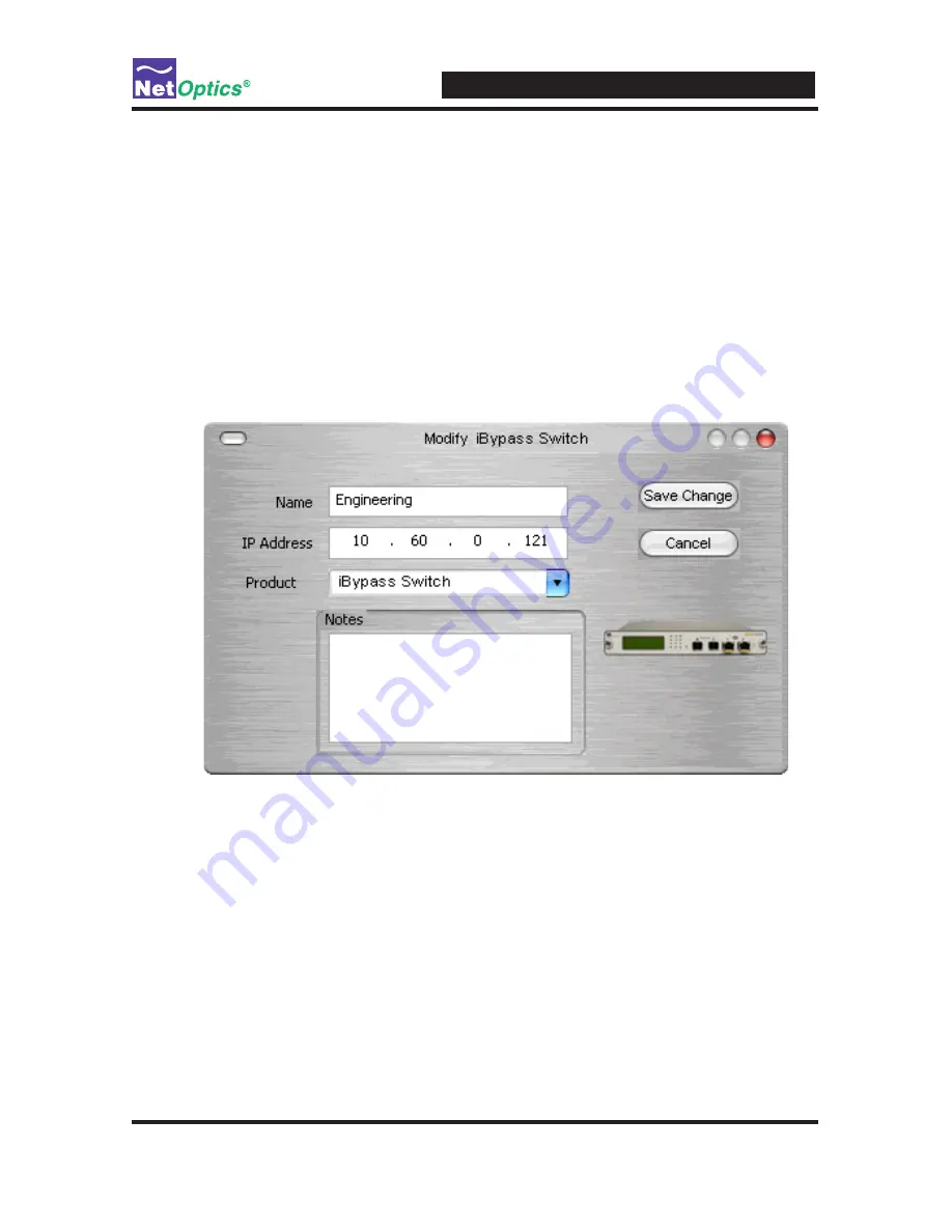
 in the toolbar. The Modify iBypass Switch dialog displays (see 

below). 

Figure 25: Modifying the iBypass Switch

3.  Change the name or IP address of the iBypass Switch. 

4.  Optionally add notes.

5.  Click

 Save Change

.


Содержание IBPO-HB50SR-XFP

Страница 1: ...User Guide 10GigaBit iBypass Switch with Heartbeat Doc PUBIBPOHBSRXFPU Rev 1 7 07 ...

Страница 2: ......

Страница 3: ...assist with installing Net Optics products into your network Trademarks and Copyrights 2007 by Net Optics Inc Net Optics is a registered trademark of Net Optics Inc iBypassTM is a trademark of Net Optics Inc Additional company and product names may be trademarks or registered trademarks of the individual companies and are respectfully acknowledged Additional Information Net Optics Inc reserves the...

Страница 4: ......

Страница 5: ... iBypass Switch 7 Connect the iBypass Switch Command Line Interface CLI 8 Configure the iBypass Switch with the CLI 9 Connect the iBypass Switch to the Network 12 Connect the Management Port to the Network 14 Connect a Monitoring Device to the iBypass Switch 15 Check the iBypass Switch Installation 15 Chapter 3 Front Panel Display 16 Utilization Alarm LEDs 17 Link LEDs 17 Power LEDs 18 Reset Butto...

Страница 6: ...er Group 32 Add Devices to a System Manager Group 32 Delete an iBypass Switch 34 Configure an iBypass Switch from System Manager 34 View iBypass Switch Information from System Manager 37 Modify an iBypass Switch Name or Address from System Manager 43 Change a Heartbeat Packet from System Manager 44 Appendix A Specifications and Models 45 Appendix B Command Line Interface 48 ...

Страница 7: ...ption IBPO HBSR XFP GigaBit SR iBypass Switch with Heartbeat IBPO HBLR XFP GigaBit LR iBypass Switch with Heartbeat IBPO HB50SR XFP GigaBit SR iBypass Switch with Heartbeat 50um Features Heartbeat Packet The iBypass Switch monitors the attached device by sending a Heartbeat packet to the device If the iBypass Switch does not receive the Heartbeat response it auto matically switches network traffic...

Страница 8: ...rnating link status can be used to trigger attached devices to send an alarm to a management system every time the iBypass Switch turns off the monitor ports When the iBypass Switch returns to bypass disabled mode the monitor ports remain on and the on off cycle is discontinued Note_____________________________________________________________________ If XFP modules from other vendors are used with...

Страница 9: ...itch Link failure Application failure Two LEDs on the front of the iBypass Switch indicate whether the switch is bypassing the connected appliance or not When the Bypass ON and an indicator is illuminated the bypass switch has not received the heartbeat packet as expected and is in bypass enabled mode When the bypass OFF indicator is illuminated the bypass switch is in bypass disabled mode and is ...

Страница 10: ... Heartbeat protects against both physical link failure and application failure on the monitoring device The bypass switch checks the path through the montoring device by sending a packet at a predetermined rate for example once every millisecond from Monitor Port 1 The iBypass Switch validates the path when it receives the packet on the Monitor Port B If the iBypass Switch does not receive the pac...

Страница 11: ...rk devices Connect the Management Port to the network Connect iBypass Switch Ports to monitoring device s Check the installation After the iBypass Switch is installed you can remotely monitor and control the iBypass Switch from either Web Manager or System Manager Plan the Installation Before you begin the installation of your iBypass Switch determine the following IP address of the iBypass Switch...

Страница 12: ...e immediately at 1 408 737 7777 Installing XFP Monitor Port Transceivers The XFP transceivers are packaged seperately You need to remove the temporary plugs from the iBypass Switch monitor slots and insert the XFP connectors into the monitor slots as shown below until they click into place 1 2 BYPASS LINK B A 1 2 ON OFF B A 1 2 OUT IN OUT IN OUT IN OUT IN RESET Network A B 1 2 Monitor Switch 10 Gi...

Страница 13: ...hat the first power supply becomes unavailable If the first power supply is unavailable the second power supply provides all power for the iBypass Switch Even if no power is available to the passive iBypass Switch network traffic flows uninterrupted Management Port RS232 Figure 4 Connecting dual power supplies Connect the power supplies to the back of the unit If you plan to use redundant power ma...

Страница 14: ... to connect an RS232 DB9 cable to the back of the iBypass Switch and to your computer To computer with terminal emulation software Management Port RS232 Figure 5 RS232 DB 9 connecting to computer Your computer needs to have terminal emulation software such as HyperTerminal to access the iBypass Switch CLI via the RS232 cable To connect the CLI 1 Connect a PC with terminal emulation software such a...

Страница 15: ...ass CLI using terminal emulation software If you are not see the instructions on the previous page The default values for this IBypass Switch are Management Port Enabled IP Address 192 168 2 100 Netmask 255 255 0 0 Threshold Port A 50 Threshold Port B 50 Threshold Port 1 50 Threshold Port 2 50 Username netoptics Password netoptics For security reasons some parameters can only be set with the CLI A...

Страница 16: ...and set username new username 2 Change the password by entering the following command set password new password 3 Record the username and password in a secure location Assign a New iBypass Switch IP Address Be sure that you have the correct new IP address for the iBypass Switch before you change the IP address value from the default 10 60 0 123 To change it Enter set ip new ip address Example Ente...

Страница 17: ...on Port B to 30 Set the Current Date and Time Enter set time mm dd yyyy hh mm ss where mm is month dd is day of the month yyyy is year hh is hour mm is minutes of the hour and ss is seconds Time is based on the 24 hour clock Display and Check Current Settings Enter show set The CLI displays the current setting similar to the example below Figure 8 Show Set command example Using the CLI Help Comman...

Страница 18: ...10 GigaBit iBypass Switch with Heartbeat 12 Figure 9 iBypass Switch CLI Help Menu 2 To view the syntax for changing the iBypass Switch configuration parameters enter help set ...

Страница 19: ... and off Connect the iBypass Switch to the Network To connect the iBypass Switch to the network 1 Connect Network Port A to the appropriate switch server or router using an LC type fiber cable Figure 10 Connect the iBypass Switch to the Network 2 Connect Network Port B to the appropriate switch server or router using an LC type fiber cable To Switch Server or Router DCE To Switch Server or Router ...

Страница 20: ...he other end to a network switch or hub Disable Enable and Check the Management Port The CLI display command toggles the display on and off From the terminal emulation software do the following 1 Enter show display to view the current setting The default value is ON 2 Enter display Now look at he front of the iBypass Switch Access from the Management Port is blocked and the iBypass Switch front pa...

Страница 21: ...ing device 1 Connect Monitor Port 1 to the appropriate port on the monitoring device using the LC type fiber cable 2 Connect Monitor Port 2 to the appropriate port on the monitoring device using the LC type fiber cable Figure 12 Connecting the Monitoring Devices 1 2 BYPASS LINK B A 1 2 ON OFF B A 1 2 OUT IN OUT IN OUT IN OUT IN RESET Network A B 1 2 Monitor To Monitoring Device To Monitoring Devic...

Страница 22: ... status LEDs located on the front panel to verify that traffic is pass ing through the switch Check the display for utilization and peak information Verify that the monitoring device is receiving traffic from the iBypass Switch Verify that the Management Port is functional by typing the iBypass Switch s IP address in your Web browser Net Optics Web Manager should appear If it does not check the Ma...

Страница 23: ...witch provides information only on the highest peak If data is not displaying as expected check the Network Port connectors for link status and activity Also check the status of the display command using the CLI see Using the Command Line Interface in chapter 2 Utilization Alarm LEDs Four LEDs indicate that utilization levels have exceeded the threshold There is one LED for incoming traffic on the...

Страница 24: ...s deployed with both power supplies both power LEDs will illuminate when connected to power If a power LED is off the corresponding power supply is not functioning or connected Reset Button Press the Reset button to reset the traffic peak and time on the display and the Utilization Alarm LEDs To prevent accidental resets the Reset button is recessed from the front panel To push the Reset button us...

Страница 25: ... monitoring devices Note _ ____________________________________________________________________ To access Web Manager Display must be set to ON from the CLI For more infor mation see Using the Command Line Interface in Chapter 2 __________________________________________________________________________ Access Web Manager Web Manager is a browser based interface that provides access to any iBypass ...

Страница 26: ...ass UP or DOWN Port A Link Status Indicates the current status of the Port A Link UP or DOWN Port 1 Link Status Indicates the current status of the Port 1 Link UP or DOWN Port A Port Speed Indicates the speed for Port A 10 Gigabit Port 1 Port Speed Indicates the speed for Port 1 10 Gigabit Power Supply 1 Status Indicates whether power is ON or OFF for this power sup ply Bypass State Indicates the ...

Страница 27: ...s The total number of packets traversing this port since the last device reset Port A Port 1 Total Bytes The total number of bytes traversing this port since the last device reset Port A Port 1 CRC Errors The number of Cyclical Redundancy Check errors on this port since the last device reset Port A Port 1 Over size Packets The total number of oversize packets traversing this port since the last de...

Страница 28: ...nnn Manager IP Address IP Address for the SNMP Manager nnn nnn nnn nnn Gateway IP Address IP Address for the default Gateway nnn nnn nnn nnn Set Port Parameters BUTTON Select to display a Port Setting window Edit HB Packet BUTTON Select to display an Edit Heartbeat window See the Check and Edit HB Packet Window section of this chapter for details about using the window Port A Port B Utilization Th...

Страница 29: ...was done at 11 AM then the Peak Rate changed to 20 at noon then 30 at 3 PM then 40 at 2 PM and then 60 at 5 PM Reset Port A Port B Statistics Reset toggle YES NO the statistics Reset Port 1 Port 2 Statistics Reset toggle YES NO the statistics Enable LFD Enable Disable Link Fault Detection Heartbeat Timeout Period s Type a number to indicate the frequency of heartbeat packets sent in milliseconds 0...

Страница 30: ...at packet or to edit the Net Optics Heartbeat packet and create your own customized Heartbeat packets one for each monitored device You can do this from Web Manager or System Manager From Web Manager do the following to view or change the heartbeat packet Figure 15 Web Manager 1 Click Check HB Packet on the Web Manager main window You see the Heartbeat Packet window shown next ...

Страница 31: ...5 Figure 16 Heartbeat Packet Window 2 Change the hexadecimal values be sure to adhere to IP address and MAC address conventions 3 Click Submit the Packet to save the changes 4 Click Go Back to Main Menu to return to the main Web Manager window ...

Страница 32: ...ettings to view system status and retrieve data from configured Net Optics iBypass Switch devices The following topics are covered Install System Manager Explore System Manager Create a Sytem Manager Group Delete a Sytem Manager Group Add iBypass Switches to a Group Delete an iBypass Switch Configure an iBypass Switch View iBypass Switch Information Change a Heartbeat Packet from System Manager ...

Страница 33: ...eement select I Agree and click Next to install System Manager The Welcome dialog appears 3 Click Next The Select Installation Folder dialog box appears 4 To install in the default folder select the default path in the Folder text box To install in a different location either type the path in the Folder text box or click Browse to find another location 5 To check the space available for System Man...

Страница 34: ...e features and functions of System Manager With System Manager you can Create iBypass Switch groups Add and delete iBypass Switches from the system Remotely configure iBypass Switches View traffic utilization and peaks View traffic statistics NOTE____________________________________________________________________ In order to access an iBypass Switch with System Manager the Display option must be ...

Страница 35: ...ration and Control information for the selected unit Tip ______________________________________________________________________ To use pop up menu shortcuts click your right mouse button in the System Frame __________________________________________________________________________ Using the Toolbar The following figure shows the System Manager toolbar Figure 19 Toolbar The table below describes th...

Страница 36: ...em Manager Create a System Manager Group Organize iBypass Switches or other Net Optics devices into groups for quick ac cess Devices must belong to a group If you add an iBypass switch when there is no group a group is created automatically To create an iBypass Switch group 1 Click New Group in the toolbar A new group bar appears in the System Frame as shown in the following figure Figure 20 New G...

Страница 37: ...t click the group that you want to delete 2 Select Delete from the pop up menu The group and all associated devices are deleted from System Manager Add Devices to a System Manager Group To configure and control iBypass Switches with System Manager you must add each iBypass Switch to a group Once you have added an iBypass Switch you can configure modify and delete it from System Manager Note _ ____...

Страница 38: ...ach Node Name in the system must be unique 4 Enter the IP address of the iBypass Switch in the IPAddress text box The IP address must be unique on the network 5 Enter any relevant information about the iBypass Switch in the Notes text box 6 Check your settings and click Create The System Manager now shows the iBypass Switch in the system see the next figure ...

Страница 39: ...Switch you are adding to System Manager Tip ______________________________________________________________________ To change the display order of iBypass Switches click and drag them into the desired order __________________________________________________________________________ Delete an iBypass Switch from System Manager You can delete an iBypass Switch from System Manager when you remove an iB...

Страница 40: ... System Manager Set the configuration parameters of an added iBypass Switch from the Configure tab To configure an iBypass Switch 1 Click the icon of the iBypass Switch you want to configure 2 Click the Configure tab Figure 23 iBypass Switch Configure Tab 2 Click the value field for the parameter you want to configure 3 Select an option from the drop down list or enter a new value from your keyboa...

Страница 41: ...rt A ex ceeds 50 utilization Port B Utilization Threshold Percentage level at which this port use triggers an alarm as default the Port B alarm is triggered when Port B ex ceeds 50 utilization Port 1 Utilization Threshold Percentage level at which this port use triggers an alarm as default the Port 1 alarm is triggered when Port 1 ex ceeds 50 utilization Port 2 Utilization Threshold Percentage lev...

Страница 42: ...seconds Heartbeat Timeout Period s Number of milliseconds between Heartbeat Packets sent from the iBypass unit to a connected monitoring device The default is 1 second Heartbeat Retries Number of heartbeats that do not come back from a de vice before an iBypass unit stops sending traffic through that monitoring device the default is 3 Heartbeat packets continue to be sent and if one comes back fro...

Страница 43: ..._________________________________________________________ Fields that have been updated since the last refresh display with a circle and arrow just to the left of the value field __________________________________________________________________________ The following table describes the status fields Field Description System Status UP DOWN Bypass Model Fiber Heartbeat Bypass Model Number Port Spee...

Страница 44: ...that define the packet type The payload bytes are all 0 s and the last four bytes are the packet checksum CRC set txpacket 00 50 c2 3c 60 00 source address 00 50 c2 3c 60 01 destination address 81 37 ff ff packet type 00 30 00 00 00 00 40 04 ec a2 c6 13 01 02 c6 13 01 01 00 00 00 00 00 00 payload bytes 00 00 00 00 00 00 00 00 00 00 00 00 00 00 00 00 00 00 00 00 a0 07 37 99 CRC Bypass State ON or O...

Страница 45: ...RC errors are the most common Ether net packets are encapsulated in a MAC frame that contains a preamble and a post envelope CRC check The Ethernet adapter on the sending station creates the preamble inserts the packet data addressing protocol data etc calculates a CRC checksum and inserts it at the end of the packet If the receiving station determines that the checksum is incor rect the packet is...

Страница 46: ...he Modify option in the menu The second method is described here To change a switch name or IP address from the Modify iBypass Switch dialog 1 In the System Frame select the image of the iBypass Switch you want to change 2 Click Modify in the toolbar The Modify iBypass Switch dialog displays see below Figure 25 Modifying the iBypass Switch 3 Change the name or IP address of the iBypass Switch 4 Op...

Страница 47: ...to 50 C Storage Temperature 10 C to 70 C Relative Humidity 10 min 95 max non condensing Mechanical Dimensions 1 350 high x 12 435 deep x 8 75 IBPO HBSR XFP and IBPO HBLR XFP Connectors 1 DB9 RS232 configuration port 1 RJ45 management port 2 XFP monitoring ports 2 SR LC network ports or 2 LR LC network ports Indicators 1 2x16 Character LCD 4 Link LEDs Fiber Model 4 Threshold Alarm LEDs 2 Power LEDs...

Страница 48: ...40 1 25 dB 1 25 dB 50 50 1 25 dB 1 25 dB Transceiver Specifications 10 GigaBit SR 850nm VCSEL 10 GigaBit LR 1310nm Laser Split Ratios Fiber Model 60 40 and 50 50 Software iBypass Command Line Interface Any terminal emulation software Web Manager Any browser Net Optics System Manager Windows 98 Windows 2000 Windows XP Certifications Fully RoHS compliant Available Models Models IBPO HBSR XFP iBypass...

Страница 49: ...ith each CLI command Commands include Help Set Reset Show Echo Display Command Sub Command Syntax Description Help Set help set Displays the set command options Reset help reset Displays the reset command options Show help show Displays the show command options Echo help echo Displays the echo command options Display help display Displays the display com mand options ...

Страница 50: ...er Port set parameter port ID parameter Where port ID is A B C or D and parameter is 0 GigaBit other variables not applicable Threshold Port set threshold port ID parameter Where port ID is A or B and parameter is 0 to 100 of available bandwidth Time set time date time Where date time is mm dd yyyy hh mm ss Username set username username Where username is the authorized user s name 8 characters or...

Страница 51: ...charac ter from being displayed on the screen Display n a display Toggles the front panel display and remote interface on and off Configuring the Heartbeat From the CLI you can set Command Sub Command Syntax Description Set Time out Set Time out Time out period 0 100 Re try Set Re try fre quency Re try 0 255 Note _ ____________________________________________________________________ At present tim...

Страница 52: ...10 GigaBit iBypass Switch with Heartbeat 46 ...

Страница 53: ... 2007 by Net Optics Inc All Rights Reserved www netoptics com ...

Отзывы: