16
S C R A P E R A D J U S T M E N T
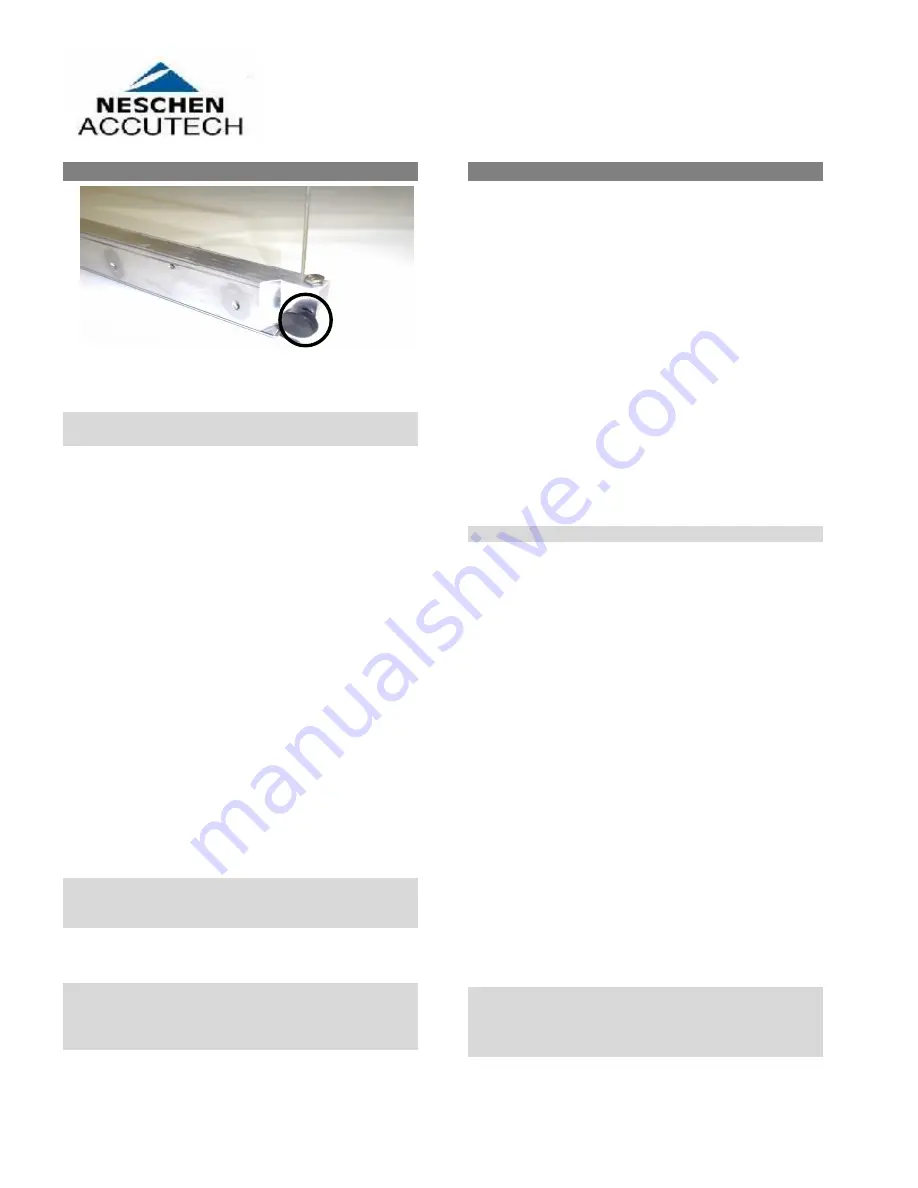
Figure 20: Scraper Bar and M4
Adjustment Screws
NOTE: The scraper adjustment must be done
with lacquer in the lacquer container.
1. Set the transport mode switch to the STOP mode.
2. Open the lacquer container door.
3. Remove the scraper bar by removing the two
thumbscrews that are holding it in place.
4. Two M4 Hex head screws are located just above
the thumbscrews that attach the scraper assembly
to the lacquer container. They are used to adjust
the scraper pressure against the top nip roller.
Extending the screws will drive the scraper bar
down and in turn will exert more force on the
scraper blade.
5. Start with the two M4 Hex head screws screwed
all the way in. Attach the scraper bar to the
lacquer container using the two thumbscrews.
6. Run test prints by following the instructions in the
“Test Procedure” section. Check the prints. If
they are not to satisfaction, extend the two M4
screws slightly and run the test procedure again.
Continue this process until the prints meet your
satisfaction. You may then proceed to the
“Processing Images” section.
NOTE: The best set point for the scraper bar is a
clean print back with the least amount of
scraper pressure.
NOTE: Be aware that faint small streaks on the
back of the print may be due to nicks or
cuts in the edge of the scraper and won’t
disappear with more scraper pressure.
T E S T P RO C E D U R E
1. Set the transport mode to RUN.
2. Turn the motor speed adjustment knob to “10.”
Check the crack between the top metal roller and
middle silicone rubber roller for excess lacquer.
Allow a couple of minutes of run time for excess
lacquer to disappear. Excess lacquer between the
rollers will be picked up by the material and will
coat both sides of the leading edge of the material.
If excess lacquer does not disappear:
a) Check the scraper. It may not be scraping
properly.
b) Check the roller adjustment. Rollers may be
adjusted too loose. Turn the roller height
adjustment screws 1/4 turn clockwise and
wait two minutes for excess lacquer to
disappear.
NOTE: Feed images into the machine face down.
3. Turn the motor speed knob to “5.” Set the
transport mode to RUN and coat several 18 x 24
prints and check the following:
a) The prints should be “dry” exiting the
machine. They may feel damp but the lacquer
should not be wet (come off on your fingers),
and stacked prints should not stick to each
other. If the prints are not “dry” enough,
slow the speed of the machine to extend the
drying time.
b) Check the coating on the test prints for
recurring marks. If the coating roller has a
defect, the mark will repeat every 4.5” (11.4
cm), the circumference of the roller. Check
the coatings for evenness of application. The
whole surface should be uniformly coated;
there should be no bare spots and no thick or
oddly textured areas.
c) Check the backs of the prints. They should
be clean with no lacquer streaking. If they are
not clean, increase the scraper pressure.
N
OTE: Whenever running machine in Idle Mode for
extended periods, dust may collect. Be sure to
allow machine to operate in RUN Mode for a few
minutes prior to processing images so that the fans
can purge any dust/debris that may have collected.


