background image


INSTALLATION INSTRUCTIONS 

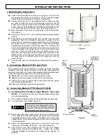
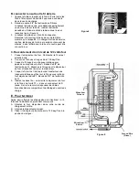
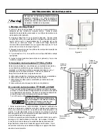
Even with the main power switch 
turned off, the wires on the utility side 
of the main breaker are still live and 
contact with them can cause serious 
injury or death. 


To Transfer Switch 

Conduit 
Connector 

Typical 
Main 
Breaker 
Location 

Live Wires on 
Utility Side of 
Main Breaker 

Figure 3 


Figure 2 

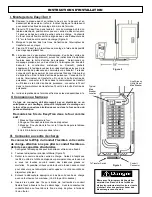
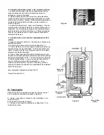
I.  Mounting the 

Easy/Tran


®


A. 

Loosen  the  front  plate  by  removing  one  screw  on  the  front  and 
loosening the two screws on the bottom.  Tilt the front plate forward 
to access the mounting holes in the back of the cabinet.  

B. 

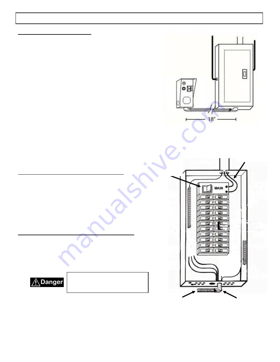
Position the 

Easy/Tran TF

 in the desirable location.  When mounting 

the  suffix  W  model  next  to  an  electrical  panel,  position  so  that  its 
bottom center is about 18 inches from the bottom center of your load 
center.  The end of the flexible conduit whip should be lined up with 
a 1/2” knockout hole on the bottom of your load center (Figure 2).   

C. 

Mark the position of the three mounting holes of the transfer switch 
with a pencil. 

D. 

Secure the 

EasyTran  TF 

to the mounting surface using appropriate 

anchors. 

E. 

When  feeding  the  generator  power  from  a  power  inlet  box  (sold 
separately),  follow  the  installation  instructions  provided  with  the 
power inlet box.  Select a convenient knockout on one of the sides of 
the  transfer  switch.    Run  building  wire  or  Romex®,  (purchased 
separately) as approved by local electrical code, from the power inlet 
box to the transfer switch. Use three of the yellow wire connectors to 
connect the leads in the transfer switch to the wire from the power 
inlet  box.    Connect  the  black  wire  from  the  transfer  switch  to  the 
black  wire  from  the  power  inlet  box;  connect  the  white  wire  in  the 
transfer  switch  to  the  white  wire  from  the  power  inlet  box:  connect 
the  green  wire  in  the  transfer  switch  to  the  green  wire  from  the 
power inlet box. 

F. 

Tilt  front  plate  back  into  the  cabinet  and  attach  with  the  screws  in 
Step 1.  

II.  Connecting  Models TF151 and TF201 

These  models should  be connected  by  a  licensed  electrician  or heating 
contractor  since  they  involve  mounting  on the  furnace  and making  the 
electrical connections on or in the furnace instead of the electrical panel.  
Connect the wires from Easy/Tran to the furnace as follows:  

A.


Black

 wire to the wire or wires that power(s) the furnace.  

B.


Red

 wire to the wire coming from the branch circuit breaker.   

C.

  White  wire  to  both  the  neutral  wire  to  the  furnace  and  the  neutral 

wire from the electrical panel.   

D.

 Green wire to the grounding point in the furnace. 


III.  Connecting Models TF151W and TF201W 

A.  Connecting the Flexible Conduit Whip to Your Load 

Center 

– Be careful not to bend the flexible conduit whip beyond 

its structural capabilities.


1. 

Set up battery-powered lighting to clearly illuminate your work area. 

2. 

Turn off the main utility breaker (Figure 3). 


3. 

Remove the cover of your load center.  Keep in mind that the wires 
on  the  utility side  of the main  breaker  are still  live  and  if contacted 
could cause serious injury or death.  If available, use a non-contact 
voltage detector to insure that the power is off on the non-utility side 
of the main breaker. 

4. 

Remove  the  appropriate  knockout  hole  in  the  bottom  of  your  load 
center with a screwdriver and hammer.  (See step I-B above.)   

5. 

Insert  all  four  of  the  wires  extending  from  the  end  of  the  flexible 
conduit  whip  through  the  knockout  hole.    Fasten  the  conduit 
connector attached to the whip into the knockout hole using the nut 
provided.   


Even with the main power switch turned 
off, the wires on the utility side of the main 
breaker are still live and contact with them 
can cause serious injury or death. 
Содержание Reliance Controls Easy/Tran TF151

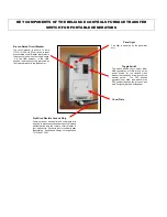
Страница 1: ...Transfer Switch 4 Yellow Wire Connectors SAFETY SYMBOLS USED IN THIS MANUAL Danger indicates an imminently hazardous situation that if not avoided could result in death or serious injury Warning indicates a potentially hazardous situation that if not avoided could result in death or serious injury Caution indicates a potentially hazardous situation that if not avoided may result in minor or modera...

Страница 2: ... either GEN generator or LINE utility as the power source for the furnace circuit breaker that has been wired through the transfer switch The OFF position generally is not used as a switch in the OFF position removes the furnace circuit both from generator and utility power Pre Wired Flexible Conduit Whip Contains two hot one neutral and one ground wire required to make connections between the fur...

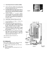
Страница 3: ... the power inlet box connect the green wire in the transfer switch to the green wire from the power inlet box F Tilt front plate back into the cabinet and attach with the screws in Step 1 II Connecting Models TF151 and TF201 These models should be connected by a licensed electrician or heating contractor since they involve mounting on the furnace and making the electrical connections on or in the ...

Страница 4: ...wire that is attached to it 2 Find the black and red wires from the Easy Tran TF 3 Cut the red wire at a length convenient for it to reach to the furnace circuit breaker Strip 5 8 from the end of the wire Connect the red wire to the furnace circuit breaker and retighten the screw on the breaker 4 Cut the black wire from the transfer switch to a length convenient for attaching it to the wire you re...

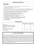
Страница 5: ...Available 1 2 or 3 4 2 2 Cabinet Dimensions H x W x D inches 7 1 2 x 7 x 4 1 2 7 1 2 x 7 x 4 1 2 Cabinet Type NEMA 1 1 Five Year Limited Warranty Reliance Controls Corporation Reliance warrants this Protran Manual Transfer Switch Switch to be free from failure to perform as intended due to defects in materials and workmanship for a period of five 5 years from date of manufacture provided the Switc...

Страница 6: ...sfert de Circuit unique de 20 ampères TF201 1 Connecteurs de fil jaune SYMBOLES DE SÉCURITÉ UTILISÉS DANS CE MANUEL DANGER indique une situation dangereuse imminente qui si ne pas évitée peut entraîner des blessures graves voire la mort Avertissement indique une situation potentiellement dangereuse qui si ne pas évitée pourrait entraîner des blessures graves ou la mort Attention indique une situat...

Страница 7: ...ctionner les GEN générateur ou ligne utilitaire comme source d alimentation pour le disjoncteur de la fournaise qui a été reliée par l intermédiaire de l interrupteur de transfert Position d arrêt en général ne sert pas comme un interrupteur en position OFF supprime le circuit four du générateur et réseau électrique Pré câblé Conduit Flexible fouet Contient deux chauds un neutre et un conducteur d...

Страница 8: ...r de transfert au fil blanc de la boîte d entrée de puissance connecter le fil vert dans le commutateur de transfert au fil vert de la boîte d entrée de puissance L Inclinez le platine dans l armoire et fixer avec les vis desserrées à l a II Connexion au fourneau Ce type de connexion doit être rempli par un électricien ou un entrepreneur en chauffage puisqu ils impliquent de montage sur le four et...

Страница 9: ... 1 Couper le disjoncteur du four Débrancher le fil qui est attaché à elle 2 Trouver les fils noirs et rouges de la TF Easy Tran 3 Coupez le fil rouge à une longueur pratique pour parvenir au disjoncteur du four Bande de 5 8 de l extrémité du fil Branchez le fil rouge sur le disjoncteur du four et resserrez la vis sur le disjoncteur 4 Couper le fil noir de l interrupteur de transfert sur une longue...

Страница 10: ...re de charge ampères 20 20 Wattmètres No No Nombre d entrées défonçables disponible 1 2 ou 3 4 2 2 Armoire Dimensions H x l x P po 7 1 2 x 7 x 4 1 2 7 1 2 x 7 x 4 1 2 Armoire Type NEMA 1 1 Garantie limitée de cinq ans Reliance Controls Corporation Reliance garantit cet Protran manuel commutateur de transfert Switch sont exempts de défaut de fonctionner comme prévu en raison de défauts de matériaux...

Страница 11: ...erencia del solo circuito de 20 amperios TF201 2 conectores de cable amarillo SAFETY SYMBOLS USED IN THIS MANUAL PELIGRO indica una situación inminentemente peligrosa que si no se evita podría causar la muerte o lesiones graves ADVERTENCIA indica una situación potencialmente peligrosa que si no se evita podría causar la muerte o lesiones graves Precaución indica una situación potencialmente peligr...

Страница 12: ... disyuntor de calentador que ha sido cableado a través del interruptor de transferencia La posición de apagado generalmente no se utiliza pues un interruptor en la Látigo flexible precableado del conducto Contiene dos cables calientes uno neutro y un cable de tierra requeridos para hacer conexiones entre el interruptor de transferencia del horno y el disyuntor del calentador en su centro de carga ...

Страница 13: ...a en el calentador III conexión de los modelos TF151AW y 201AW Cómo conectar el látigo flexible de conductos a su centro de carga por favor no intente doblar el látigo flexible de conductos más allá de sus capacidades estructurales Configure la iluminación alimentada por batería para iluminar claramente su área de trabajo Turn off the main utility breaker Figure 3 1 Retire la cubierta de su centro...

Страница 14: ...ros y rojos del Easy Tran TF 3 Corte el alambre rojo en una longitud conveniente para que alcance al disyuntor del calentador Tira 5 8 del extremo del cable Conecte el cable rojo al disyuntor del horno y vuelva a apretar el tornillo del interruptor 4 Corte el cable negro del interruptor de transferencia a una longitud conveniente para fijarlo al alambre que usted quitó del disyuntor del calentador...

Страница 15: ...isponibles 1 2 o 3 4 2 2 Dimensiones del gabinete H x W x D pulgadas 7 1 2 x 7 x 4 1 2 7 1 2 x 7 x 4 1 2 Tipo de gabinete NEMA 1 1 GARANTÍA LIMITADA DE CINCO AÑOS La Corporación Controls de dependencia confianza garantiza que este interruptor de transferencia manual protran switch esté libre de fallas para realizarse como se ha previsto debido a defectos en materiales y mano de obra por un período...

Страница 16: ...Reliance Controls Customer Service 800 439 5745 Website www reliancecontrols com Reliance Controls Service à la clientèle 800 439 5745 Website www reliancecontrols com IITWF 12 12 17 ...

Отзывы: