FlexFilter
EN
Contact your nearest authorized distributor or
N
$
e
$
d
$
e
$
r
$
m
$
a
$
n
$
for advice on technical service or
if you require help with spare parts. See also
w
$
w
$
w
$
.
$
n
$
e
$
d
$
e
$
r
$
m
$
a
$
n
$
.
$
c
$
o
$
m
$
.
7.1 Ordering spare parts
When ordering spare parts always state the following:
• The part number and control number (see the
product identification plate).
• Detail number and name of the spare part (see
w
$
w
$
w
$
.
$
n
$
e
$
d
$
e
$
r
$
m
$
a
$
n
$
.
$
c
$
o
$
m
$
/
$
e
$
n
$
/
$
s
$
e
$
r
$
v
$
i
$
c
$
e
$
/
$
s
$
p
$
a
$
r
$
e
$
-
$
p
$
a
$
r
$
t
$
-
$
s
$
e
$
a
$
r
$
c
$
h
$
).
• Quantity of the parts required.
8 Recycling
The product has been designed for component mater-
ials to be recycled. Different material types must be
handled according to relevant local regulations. Con-
tact the distributor or
$
N
$
e
$
d
$
e
$
r
$
m
$
a
$
n
$
if uncertainties arise
when scrapping the product at the end of its service
life.
9 Instructions for special modules
The following modules are covered, see
• Level 1: RF top modules (1B, 1C) and cyclone top
module (1D).
• Level 2: Cyclone insert (2D).
• Level 4: Stand (4 C–F) and wall mounting brackets
(4G).
• Level 5: Inlet cyclone module (5D).
• Level 7: Automatic emptying / automatic feeding
out modules (7D and 7H).
9.1 RF Top
See
items 1B and 1C.
WARNING! Risk of personal injury
RF top modules are fitted with compressed air
cylinders that can cause severe personal in-
jury. The compressed air supply must be shut
off before service work is carried out. Pressing
the Manual Function button a few times will re-
lease any residual pressure. Ensure the vacuum
unit can not start by switching off the main-
tenance switch and/or the main switch on the
starter.
9.1.1 Function
–
show schematically the function
of a FlexFilter Twin RF. During normal operation, the
function is the same as for a basic FlexFilter.
See
. When filters are cleaned, the valve
(a) closes the outlet from the FlexFilter and valve (b)
opens to atmosphere. Air is sucked with considerable
power through valve (b) and flows in a reverse direc-
tion downwards through the filter socks. The dust is
dislodged and falls into the bin. The air then flows in-
to the other side of the FlexFilter, upwards through
the filter socks into the top module. From here it con-
tinues to the vacuum unit. A connected control unit
ensures that the next cleaning cycle cleans the other
half of the filter socks.
Single RF works in the same way but here the top
module is divided into two chambers so that half the
filter socks are cleaned in one cycle and the other half
in the next cycle.
. In particularly difficult cases an addi-
tional valve (c) can be installed. This valve is normally
open but closes during filter cleaning. Now, for a short
moment, the full capacity of the vacuum unit is avail-
able for filter cleaning. No air comes through the pipe-
work. For connecting this optional valve, see the rel-
evant manual.
–
show pneumatic schematics for
Single RF and Twin RF.
9.1.2 Maintenance
The RF top needs no special maintenance. Before
emptying the dust collecting bin, manual filter clean-
ing should be carried out a couple of times. The vacu-
um unit should be running. A distinct change in sound
reveals the function. The same procedure should be
followed at approximately monthly intervals for Flex-
Filters with automatic emptying.
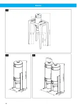
9.2 Stands and wall brackets
. Large dust collecting bins and automat-
ic emptying devices require stands (4 C–F) instead of
legs. In some cases, wall brackets (4G) are preferred
to legs or stands.
A separate wall bracket is available for this unit and
must be installed when the FlexFilter is wall mounted.
Wall brackets are supplied in pairs, a left-hand and a
right-hand bracket. A FlexFilter Single requires one
pair and a Twin requires two.
9.2.1 Safety
The stand should be securely anchored to the found-
ation. The foundation should be level and firm. A con-
crete foundation and expanding bolts are recommen-
ded, particularly if the FlexFilter has been fitted with
an explosion relief panel. Should a dust explosion oc-
cur, strong side forces may be generated. The stand
is not a work platform and is not fitted with steps or a
rail.
The wall brackets should be anchored to a wall or pillar
that is sufficiently solid, with adequate bolts. A Single
FlexFilter can weigh 500 kg (1100 lbs) when the bin is
full. In extreme cases, the weight may be even high-
er if the material is heavy and emptying has been neg-
lected.
The automatic feeding out device (see
7H) weighs 86 kg (189 lbs).
24
Содержание FlexFilter
Страница 8: ...FlexFilter Figures A B C D 1 A B C D 2 4 3 A B D 5 A B C 6 A B C 7 A B C D F G H A B C F G 1 8...
Страница 9: ...FlexFilter A B C D E F 2 9...
Страница 10: ...FlexFilter 3 4 5 10...
Страница 11: ...FlexFilter 6 7 8 11...
Страница 12: ...FlexFilter 9 10 11 12 12...
Страница 13: ...FlexFilter 800 mm 31 5 13 funktion Manual 0 6 0 7 MPa 6 7 bar 85 100 PSI 24 V AC 14 RF RF 15 16 17 18 13...
Страница 14: ...FlexFilter Min 2100mm 83 19 B A C 20 21 b a c A B 22 14...
Страница 16: ...FlexFilter 25 16...
Страница 152: ...www nederman com...

