2
1.2.3. Corner Installation
1.2.1.
Positioning the Heater
Review the necessary clearances specified in this section
before considering where to position the heater.
Also, check the practicability of installing the flue system in
relation to any obstructing roof beams before positioning the
heater.
The clearance distances can only be reduced if the
surrounding walls are made of non-combustible material such
as stone, brick, or concrete. If non-combustible material,
distance can be reduced to 100 mm. Alternatively, shielding
the wall(s) can reduce clearances (refer to the next section for
more detail).
Clearances to combustible surfaces vary depending on the
type of flue shielding used.
1.2.2.
Standard Installation
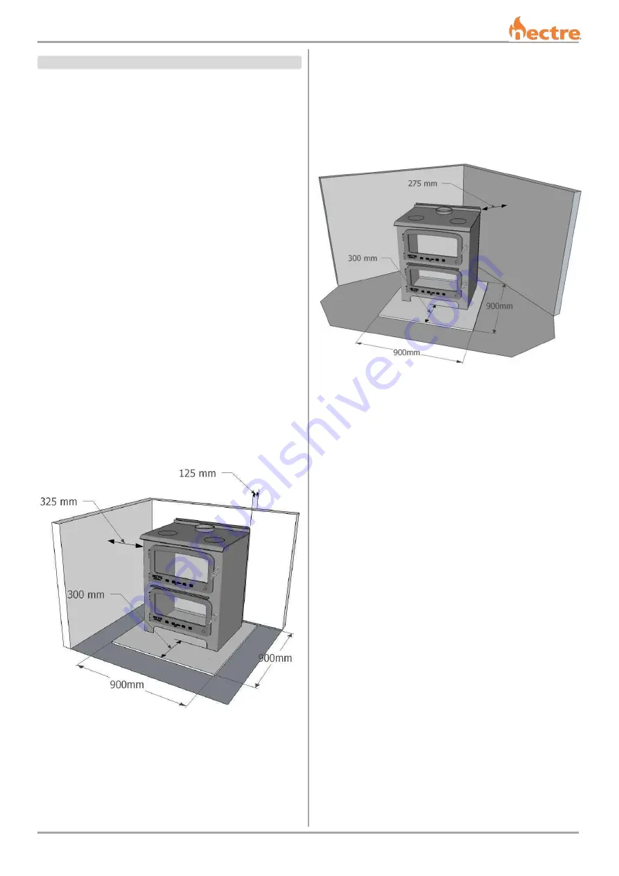
Dimensions given in the image below represent the minimum
clearance (in millimeters) to combustible materials.
Side clearance = 325mm
Rear clearance = 125mm
Dimensions given in the image below represent the minimum
clearance (in millimeters) to combustible materials.
Corner clearance = 275mm
1.2.4. Floor Protector
Unless the heater is standing on a heat resistant floor such as
concrete slab with slate or tiles, it will be necessary to
provide a floor protector.
The minimum required dimensions for the floor protector are
shown in the previous images. It must extend no less than
300mm in front of the door opening, no less than 200mm
either side of the door opening, and extend under the heater.
Minimum dimensions for the floor protector are 900mm wide
by 900mm deep. It may be desirable, for example, aesthetic
reasons, for the floor protector to be larger than these
minimum dimensions.
The floor protector shall be constructed of non-combustible
material no less than 15mm thick and with a thermal
conductivity not greater than 0.33W/m °K, e.g., compressed
cement sheet OR 7mm tile underlay and 8mm tiles.
The floor protector may be laid directly on the combustible
floor.
1.2.
INSTALLING THE HEATER


