background image

Chapter 2 TROUBLESHOOTING

2-29

NWA-033627-001 Rev.4.0

95ch2001.fm

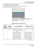
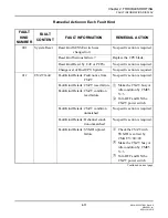
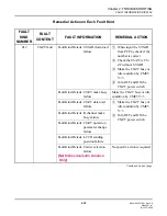
FAULT INFORMATION DISPLAY

Remedial Action on Each Fault Kind

FAULT 

KIND 

NUMBER

FAULT 

CONTENT

FAULT INFORMATION

REMEDIAL ACTION

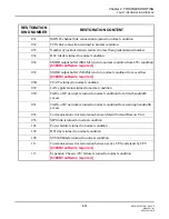
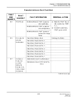
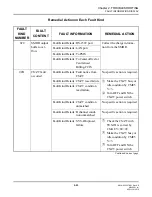
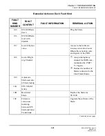
10D

Lack of High-
way Channel 
for data com-
munication

Confirm if the highway chan-
nel for ISDN communication 
is correctly set (CM05 Y=2).

10E

Illegal use of 
CPU blade for 
Remote Unit 
only

Replace the blade for SV8300.

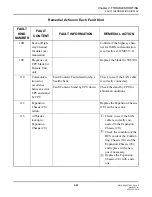
110

Communica-
tion error 
occurrence 
between active 
CPU and stand 
by CPU

Fault Content: Fault detection by a 
health check

Check to see if the LAN cable 
is correctly connected.

Fault Content: Stand by CPU down

Check the stand by CPU for 
abnormal conditions.

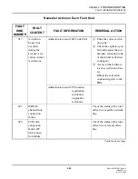
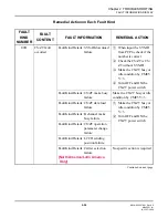
112

Expansion 
Chassis (2U) 
failure

Replace the Expansion Chassis 
(2U) with a new one.

116

All blades 
lockup in 
Expansion 
Chassis (2U)

Check to see if the LAN 
cable is correctly con-
nected to the Expansion 
Chassis (2U).
Check the condition of the 
BUS cards of the Control-
ling Chassis (1U) and the 
Expansion Chassis (2U), 
and replace with a new 
one if necessary.
Replace the Expansion 
Chassis (2U) with a new 
one.

1

2

3

APRIL/16/2010

Содержание SV8300

Страница 1: ...System Maintenance Manual NWA 033627 001 ISSUE 4 0...

Страница 2: ...ration has prepared this document for use by its employ ees and customers The information contained herein is the property of NEC Corporation and shall not be reproduced without prior written approval...

Страница 3: ...Service Conditions 1 5 Fault Message 1 5 External Alarm Display Panel 1 5 Programming Procedure 1 6 Fault Message 1 6 External Alarm Display Panel 1 15 Operating Procedure 1 15 STATION LINE STATUS DI...

Страница 4: ...mming Procedure 1 49 PING COMMAND 1 52 General Description 1 52 Service Conditions 1 52 Programming Procedure 1 55 Operating Procedure 1 56 Chapter 2 TROUBLESHOOTING PRECAUTIONS 2 2 Grounding Requirem...

Страница 5: ...4 0 95toc001 fm Station Line Fault 2 40 C O Line Tie Line Fault 2 42 Power Failure Transfer PFT Fault 2 51 Digital Multiline Terminal Fault 2 52 IP Station Fault 2 54 DESKCON Fault 2 56 DSS Console F...

Страница 6: ...iv NWA 033627 001 Rev 4 0 95toc001 fm THIS PAGE LEFT BLANK INTENTIONALLY JULY 17 2009...

Страница 7: ...v 4 0 95ch0001 fm PURPOSE INTRODUCTION PURPOSE This manual explains the maintenance services provided with the SV8300 and the recommended trouble shooting procedure when a fault has occurred for maint...

Страница 8: ...SERVICES This chapter describes the general description service conditions programming and operating procedure of the maintenance services CHAPTER 2 TROUBLESHOOTING This chapter describes the precaut...

Страница 9: ...ly unless we need to mention the type of terminal in particular TERMINAL NAME PRODUCT NAME Multiline Terminal Digital Multiline Terminal Dterm Dterm 70 Elite Dterm 75 Series E Dterm 85 Series i DT300...

Страница 10: ...the IP terminal by attaching the IP Adapter IP Enabled Digital Multiline Terminal This terminal provides users with all fea tures currently available in IP Station TERMINAL NAME PRODUCT NAME Multilin...

Страница 11: ...nual Contains the Customer Administration Terminal CAT operation command functions and data re quired for programming the system PC Programming Manual Contains the functional description and the insta...

Страница 12: ...the system data backup before the following operations Turning Off the system System Reset reset of CPU blade Changing the CPU blade to Off Line Mode Changing the CPU blade to On Line Mode after syst...

Страница 13: ...v 4 0 95ch1001 fm Chapter 1 UNIVERGE SV8300 System Maintenance Manual MAINTENANCE SERVICES This chapter describes the general description service conditions programming and operating procedure of the...

Страница 14: ...and marking are as follows 1 1st Data 2 2nd Data Default With the system data clear command CM00 CM01 the data with this marking is automatically assigned for each command Command with this marking c...

Страница 15: ...displays the fault information on the PCPro or the Customer Administration Terminal CAT For CAT operation refer to the Command Man ual The display format using PCPro is shown below The fault informati...

Страница 16: ...umber assigned to the fault infor mation Occurrence Date and Time field Displays the date and time at which the fault occurred Error Type field Displays the number of the fault type Alarm field Displa...

Страница 17: ...ared by CMEA Y 0 F from PCPro CAT 4 External Alarm Indication of external equipment can be cleared by CMEA Y 1 00 01 02 from PCPro CAT 5 External Alarm Indication is cleared when the turn off the syst...

Страница 18: ...External Alarm Kind 0 Fault Memory store No output of External Alarm 1 Fault Memory store External Alarm is MN alarm 2 Fault Memory store External Alarm is MJ alarm 3 No Fault Memory store No Externa...

Страница 19: ...tem Upgrade 04A Long call duration information NOTE 5 061 VoIPDB Startup Process is failure 8300R4 software required 100 Power failure 102 DTI line failure 104 SV8300 Blade down 106 SV8300 Blade reset...

Страница 20: ...Alarm is MN alarm 2 Fault Memory store External Alarm is MJ alarm 3 Fault Memory store External Alarm is MN alarm 110 Communication error occurrence between active CPU and stand by CPU 8300R4 softwar...

Страница 21: ...arm is MN alarm 2 Fault Memory store External Alarm is MJ alarm 3 No Fault Memory store No External Alarm output 031 ISDN D channel link connection returned to normal condition 032 CCIS link connectio...

Страница 22: ...n error restoration between Main Unit and Remote Unit NOTE 4 0 3 External Alarm Kind 0 Fault Memory store No output of External Alarm 1 Fault Memory store External Alarm is MN alarm 2 Fault Memory sto...

Страница 23: ...o be registered into Fault Memory In this case External Alarm Kind cannot be changed NOTE 3 The fault information of the fault kind No 02C 03C is also registered to the CPU blade when the OAI fault oc...

Страница 24: ...52 is registered to the CPU blade of Main Unit at 20 seconds later from the predetermined time set by CM0B Y 1XX 80 NOTE 5 About long call duration of trunk call fault kind 04A When Long call duration...

Страница 25: ...ation No Assign the Kind of PGD 2 U10 station 1 2 Y 65 X XXXXXXXX Station No 3 External relay external key only Specify the External Key group number 1 2 Y 66 X XXXXXXXX Station No 00 63 External Key...

Страница 26: ...tion using PCPro For the way of setting Alarm kind of Fault Information using PCPro refer to PC Programming Manual DESCRIPTION DATA Assign the function of MJ MN alarm clear key to the external key 1 2...

Страница 27: ...Fault Information 01 MJ Alarm 02 MN Alarm NONE No Data NOTE When connecting the RELAY port Built in CPU blade and the MJ MN lamp of Alarm Display Panel the first data must corresponding between the RE...

Страница 28: ...e or a Multiline Terminal using the CAT or the PCPro Service Conditions This feature is not available when the system is off line Programming Procedure No programming is required Operating Procedure O...

Страница 29: ...connected cannot be displayed Software Test 01 FF See Station Status Information Page 1 22 This data is same as the status code of CMF5 INDICATION STATUS OF SINGLE LINE TEL STATUS OF DIGITAL MULTILIN...

Страница 30: ...this feature can disconnect the batteries from the PBX using the PCPro or the CAT and prevent an excessive discharge of the battery System Diagram of Battery Release Control Service Conditions The ba...

Страница 31: ...03 and 04 collectively enter 00 When the first data is entered the current status of the specified unit is displayed 1 Normal operation Enter 0 for the second data to disconnect DE EC0 EC0 ST COMMAND...

Страница 32: ...tation status information can be displayed on the PCPro or the CAT by direct command Idle Line Lockout Dialing Tone Trunk Connection reorder tone busy tone service set tone etc Types of Connection sta...

Страница 33: ...response or an invalid response from a device is received this program stores in memory the slot number of that device From the PCPro or the CAT a maintenance person can read the slot number of any d...

Страница 34: ...hold 3 party Conference Trunk 20 In Reorder Tone connection 21 In Reorder Tone connection While consultation hold a Station 22 In Reorder Tone connection While consultation hold a trunk 23 In Reorder...

Страница 35: ...ns STATUS CODE DESCRIPTION REMARKS 60 In Station to Station connection 62 In Three Way Calling 65 Holding 66 Voice Call to a Multiline Terminal 67 Voice Call from a Station 71 In Station to Trunk conn...

Страница 36: ...Information Operation For the meaning of status code see Trunk Status Information on next page DE F50 F50 ST COMMAND DE DXXX XXXXXXXX XXXXXXXXX 0 DXXX Trunk No a b c d e f g XXXXXXXXXXXXXXXXXXXXXXX h...

Страница 37: ...tation and two trunks 0D In Ringback Tone Busy Tone connection Tie Line 0E Waiting for release signal from distant office 10 Sending dialed digits Outgoing Trunk of a tandem connection 11 Three Way Ca...

Страница 38: ...7 001 Rev 4 0 95ch1001 fm DIAGNOSTICS 3 Alarm Information Operation DE F53 F53 ST COMMAND DE XXXX XXXXXXXX XXXXXXXXX XXXX Memory Dump Data a b c XXXXXXXXXXXXXXXXXXXXXX a Memory Dump Data b Designated...

Страница 39: ...ocessing Unit CPU 0001 Reason for System Reset 00 Power on 01 RESET on CPU blade 02 Endless Loop in H Rank 03 Endless Loop in L Rank 05 Stack Trouble 06 Address Trouble 07 COP Alarm 08 Abort 09 SENSE...

Страница 40: ...depends on the ambient temperature The following caution label shows battery replacement interval and attached to the CPU chassis When you set up the battery for the first time you must keep the reco...

Страница 41: ...The notification for maintenance is indicated by the alarm lamp MJ MN on the external alarm panel or the Multiline Terminal function key lamp The Multiline Terminal function key steady lights as MJ a...

Страница 42: ...eck item for periodic mainte nance 1 2 Y 3 00 07 Periodic maintenance 0 Battery check 1 7 Check item No 1 No 7 Specify the Multiline Terminal for alarm display if required 1 2 Y 16 01 Multiline Termin...

Страница 43: ...3627 001 Rev 4 0 95ch1001 fm FAULT REPORT SCHEDULING Operating Procedure To clear the alarm display Operation DE EA1 EA1 ST COMMAND DE EA1 XX XX XX XX 00 Clear all of MJ MN alarms 01 Clear MJ alarms 0...

Страница 44: ...ng When faults occur in the system you can specify the cause of faults Fault Log Collection 1 Designation of fault logs collection of station B 3 Confirmation of output fault logs Reset causes Reset t...

Страница 45: ...n amount of time about 10 seconds from SIP trunk to CPU blade a fault notification is sent and the call is restored to normal state By this feature you can avoid occupying channels if a disconnected m...

Страница 46: ...led ITR 16D 2A BK WH TEL Available when firmware of ITR 16D 3A BK WH TEL is in stalled ITR 8D 2U BK WH TEL Available when firmware of ITR 8D 3 BK WH TEL is installed ITR 16D 2U BK WH TEL Available whe...

Страница 47: ...d the error number of control sequences The fault logs are collected by the following timing When IP Stations login to the system and when the VoIPDB is in online status When you set the system data f...

Страница 48: ...currence Time XX XX XX XX XX XX YY MM DD HH MM SS NOTE 2 6 Protocol Type PROTOCOL 1 iLP PM 2 PROTIMS 4 UDP H 245 AA MEANING 01 Self Reset Before the registration Before DRS01 required a default settin...

Страница 49: ...third retry occurrence of re sending 5 Total number of packets received 6 Number of ACK request packets received 7 Total number of error packets received For PROTOCOL 4 UDP H 245 1 Total number of se...

Страница 50: ...only when the data has been notified NOTE 4 The maximum eight records of DRS No and the cause of registration NG occurrence can be displayed Four items are displayed per line however this is displaye...

Страница 51: ...ice packets sent from the terminal The number of received packets of voice log is the number of voice packets received from the terminal of the connected party The number of lost received packets of c...

Страница 52: ...imal value 8 Number of received RTP packets lost XXXXXXXX 8 digits fixed hexadecimal value Conditions for call log collection of SIP trunk are as follows a Call log of SIP trunk is notified from SIP t...

Страница 53: ...registered and the path is released The fault information fault kind 043 is registered whenever the path is released by RTP monitor ing The RTP monitoring starts when one packet is received from the...

Страница 54: ...he VoIPDB 1 2 Y 2XX VOIP Port 2 Unit No 01 50 91 0 Not provided 1 To provide Assign Service Restriction Class C to the required stations 1 2 Y 07 X XXXXXXXX IP Station No 00 15 Service Restriction Cla...

Страница 55: ...n online status 1 2 Y 6 10 Fault log collection 0 To collect 1 Not collected Specify the RS port to collect VoIP log 1 2 Y 00 0 Unit01 Port1 1 Unit01 Port2 08 VoIP log collection NONE No data Specify...

Страница 56: ...Port2 0 Low 1 High Specify the RTS signal sent to terminal for the RS port NOTE When using CPU RS 232C port for PCPro set the default 1 2 Y 06 0 Unit01 Port1 1 Unit01 Port2 0 Low 1 High Specify the da...

Страница 57: ...he following programming DESCRIPTION DATA Specify the terminals VoIPDB to collect fault logs NOTE When reading this data second data 1 is displayed normally 1 2 Y 6 11 Specification of fault log colle...

Страница 58: ...y Example When QoS Display Key is pressed while an IP Multiline Terminal communicates or HELP Key is pressed continuously while a SIP Multiline Terminal communicates with the station number 3000 the L...

Страница 59: ...ress Soft key of Exit If you do not that the QoS information will keep being displayed 5 This feature is available for the IP Multiline Terminal version 2 81 or later 6 When using this feature for SIP...

Страница 60: ...t to single line telephone Multiline Terminal virtual station virtual station for PS and built in modem The station numbers for ISDN telephone cannot be entered DATA ERROR is displayed if entered 3 Th...

Страница 61: ...ing All Calls e Call Forwarding Busy Line f Call Forwarding No Answer g Logout Call Forwarding PS out of cell zone h Do Not Disturb For details of abcdefgh refer to Table A Readout Service Status A fo...

Страница 62: ...r c Line status 0 Line is idle 1 Line is busy E Readout Error _ Underscore Off line d Call Forwarding All Calls 0 Call Forwarding All Calls is not set 1 Call Forwarding All Calls is set e Call Forward...

Страница 63: ...1 Main station number for Number Sharing E Readout Error _ Underscore No connection by CM12 Y 19 l Split Call Forwarding All Calls 0 Split Call Forwarding All Calls is not set 1 Split Call Forwarding...

Страница 64: ...irm whether a reply to the ping request is received from the terminal or not NOTE You can send a ping request only once by executing a ping command once So you can not set the ping request parameter s...

Страница 65: ...192 168 1 3 S return key To send a ping request to the IP address with 1 added to the last one Example The ping request is sent to 192 168 1 3 if you press S return key after sending it to 192 168 1...

Страница 66: ...l protection Network unreachable Host unreachable Protocol unusable Port unusable Fragmentation failed Source routing failed Destination network unknown Destination host unknown Source host isolated f...

Страница 67: ...bility that determine quality are contained within TOS Programming Procedure ICMP TYPE CLASSIFI CATION GENERAL DESCRIPTION MEANING 12 Reply error Reply message resulting by the IP header being abnorma...

Страница 68: ...ective when the reply message resulting by executing the ping com mand is displayed DE space key To send again a ping request to the same IP address as the last one hyphen key To send a ping request t...

Страница 69: ...1 NWA 033627 001 Rev 4 0 95ch2001 fm UNIVERGE SV8300 System Maintenance Manual Chapter 2 TROUBLESHOOTING This chapter describes the precautions before troubleshooting and the troubleshooting procedur...

Страница 70: ...arge as the ungrounded branch supply conductors as part of the circuit that supplies the PBX Bare covered or insulated grounding conductors are acceptable Individually covered or insulated equipment g...

Страница 71: ...ard You must wear a grounded wrist strap to protect blades from static electricity Static Electricity Guard WHEN PLUGGING UNPLUGGING A BLADE WHEN HOLDING A BLADE Continued on next page WRIST STRAP FRA...

Страница 72: ...eet for the work in which blades are handled When engag ing in such work the installer must be careful not to cause damage by static electricity WEAR A WRIST STRAP AND PERFORM THE WORK ON A GROUNDED C...

Страница 73: ...when plugging or unplugging the blade If you touch another area you may be exposed to hazardous voltages 2 You must wait for 30 seconds before plugging the blade again when unplugging the blade while...

Страница 74: ...4 0 95ch2001 fm PRECAUTIONS Turning Power ON 1 Turn the POWER switches of all the Units to ON Turning Power OFF 1 Turn the POWER switches of all the Units to OFF CAUTION Do not turn the POWER switch...

Страница 75: ...D TROUBLESHOOTING Fault Detection Method See Page 2 8 1 Alarm Indication on PCPro Alarm Display Panel 2 LED Indication on Blades 3 Complaint from station user or operator Fault Diagnosis and Troublesh...

Страница 76: ...fault has occurred in the system you can also detect the fault by LED indication on blades LED Indication on Blades shows the alarm indication LEDs on each blade Page 2 9 For details of LED indicatio...

Страница 77: ...240 IPM Flash 60 IPM Flash Flash specially ON OFF 7 3 Steady ON or OFF 120 IPM Flash S2 Green Steady ON Flash OFF ALM Red OFF Steady ON Flash LINK Green Steady ON Flash OFF 100M Green Steady ON OFF C...

Страница 78: ...teady ON OFF Steady ON Flash 100 ms Flash 1s OFF CD 4ODTA ODT LIVE LED Green Flash 120 IPM Steady ON Flash 1S OFF BUSY LED Red Steady ON OFF Steady ON Flash 100 ms Flash 1s OFF CD 4DIOPA LLC DIOP LDT...

Страница 79: ...Flash 1S OFF BUSY LED Red Steady ON OFF Steady ON Flash 100 ms Flash 1s OFF CD 8DLCA 16DLCA DLC LIVE LED Green Flash 120 IPM Steady ON Flash 1S OFF BUSY LED Red Steady ON OFF Steady ON Flash 100 ms F...

Страница 80: ...ro CAT An example of fault information display is provided below DE EA0 0 XXXXXXXXXXXXXXXX Fault Information 0 DE EA0 _ ST COMMAND S EA0 1 XXXXXXXXXXXXXXXX Fault Information 1 S EA0 2 XXXXXXXXXXXXXXXX...

Страница 81: ...n failure 025 Number of lockout stations was more than predetermined number 026 DLC blade down 028 SMDR output buffer SRAM exceeded 80 8300R3 software required 029 SMDR output buffer SRAM overflow 830...

Страница 82: ...tween CPU blade and Line Trunk blade 8300R3 software required 10D Lack of Highway Channel for data communication 8300R3 software required 10E Illegal use of CPU blade for Remote Unit only 8300R3 softw...

Страница 83: ...rflow 8300R3 software required 03B CS ZT returned to normal condition 03C LAN application returned to normal condition 050 Traffic of IP network returned to normal condition from limit bandwidth exces...

Страница 84: ...EMEDIAL ACTION 001 System Reset Reset kind Power On Initialize No specific action is required Reset kind Initialize by Reset Button SW1 Reset kind Serious failure 1 Replace the CPU blade Reset kind Se...

Страница 85: ...d 012 CS ZT fault Fault Kind Details Fault notice from CS ZT No specific action is required Fault Kind Details CS ZT reset failure Make the CS ZT busy or idle condition by CME5 Y 3 Turn OFF and ON the...

Страница 86: ...on by CME5 Y 3 Turn OFF and ON the CS ZT power switch Fault Kind Details CS ZT make busy failure Make the CS ZT busy or idle condition by CME5 Y 3 Fault Kind Details CS ZT data load failure Make the C...

Страница 87: ...ZT expansion data setting failure Fault Kind Details CS ZT operation parameter 2 change failure 016 It is a day for periodic maintenance Check Item Battery check Exchange the battery Check Item Check...

Страница 88: ...capitals sym bol and register the pre liminary activation code or the formal activation code again Access to the Software License Activation Cen ter Obtain the activation code and register to the PBX...

Страница 89: ...back onto the hook switch If the station remains in the line lockout state check the line state the line between the station and the PBX may be shorted 026 DLC blade down Alarm kind Terminal was cut o...

Страница 90: ...l failure Replace the terminal with a known good one and check to see if the same failure occurs Alarm kind Terminal Disconnected Check the cable connection between the terminal and the PBX Check to s...

Страница 91: ...rred Fault Kind Details Fault notice from CS ZT No specific action is required Fault Kind Details CS ZT reset failure Make the CS ZT busy or idle condition by CME5 Y 3 Turn OFF and ON the CS ZT power...

Страница 92: ...dition by CME5 Y 3 Turn OFF and ON the CS ZT power switch Fault Kind Details CS ZT make busy failure Make the CS ZT busy or idle condition by CME5 Y 3 Fault Kind Details CS ZT data load failure Make t...

Страница 93: ...When Terminal kind is SMDR Fault Content Connection Timeout Fault Content Connection Cut Off text receive Check to see if the LAN cable is correctly con nected Confirm the condition of the LAN device...

Страница 94: ...e CPU ex Power of HUB Confirm the program ming data for the Remote Unit over IP system which is set to the Main Unit and Remote Unit 043 SIP TRK failure Check to see if the LAN cable is correctly con...

Страница 95: ...sta tion Connection Status Call with tandem connection Connection Status Termination with tandem connection 061 VoIPDB Startup Process is failure 100 Power failure FAN Check to see if the FAN cable is...

Страница 96: ...ware License Activation Center Obtain the activation code and register to the PBX 108 Lack of High way Channel Assign the highway channel for ISDN com munication by CMF7 Y 9 again Reduce the number of...

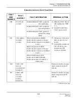
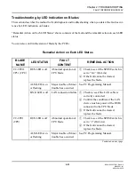
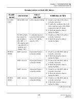
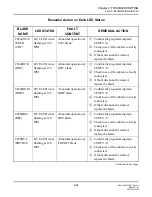
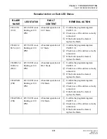
Страница 97: ...rence between active CPU and stand by CPU Fault Content Fault detection by a health check Check to see if the LAN cable is correctly connected Fault Content Stand by CPU down Check the stand by CPU fo...

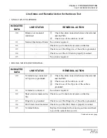
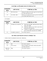
Страница 98: ...Line Status Remedial Action shows the line status and the remedial action on each indicated data Diagnose the contents of the fault and perform the remedial action by referring to Line Status and Reme...

Страница 99: ...ed 04 Check to see if the LC blade is properly mounted 05 No action is required INDICATED DATA LINE STATUS REMEDIAL ACTION 00 Terminal is not connected or Tip wire is grounded Check the cable connecti...

Страница 100: ...al with a known good one and check to see if the same failure occurs INDICATED DATA LINE STATUS REMEDIAL ACTION 00 Terminal is not connected Check the LAN cable connection between the ter minal and th...

Страница 101: ...operation of CPU blade Check to see if the SENSE switch is set to 0 4 On Line If the fault cannot be cleared replace the blade ALM LED is on or flashing Major trouble or Minor trouble has occurred See...

Страница 102: ...U Check to see if the LAN cable is correctly connected If the fault cannot be cleared replace the blade PZ BS10 BUS0 LED1 is not on Expansion Chassis 1 connection failure Check to see if the BUS cable...

Страница 103: ...the fault cannot be cleared replace the blade CD 4DIOPA DIOP LIVE LED is not flashing at 120 IPM Abnormal operation of DIOP blade Confirm the programming data CM05 Y 0 Check to see if the cable is cor...

Страница 104: ...ected If the fault cannot be cleared replace the blade CD 8DLCA 16DLCA DLC LIVE LED is not flashing at 120 IPM Abnormal operation of DLC blade Confirm the programming data CM05 Y 0 Check to see if the...

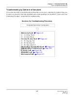
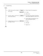
Страница 105: ...to the problem by Section for Trou bleshooting Procedure and perform the troubleshooting Sections for Troubleshooting Procedure Complaint from Station User Operator Station Line Fault Page 2 40 1 At...

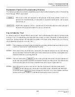
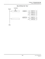
Страница 106: ...e on the fault In the following are given step by step explanations about how to use the Tree STEP1 The maintenance personnel gathers information concerning the fault and selects the tree to be used f...

Страница 107: ...ter 2 TROUBLESHOOTING 2 39 NWA 033627 001 Rev 4 0 95ch2001 fm FAULT INFORMATION DISPLAY How to Follow the Tree START END Symptom STEP 2 STEP 3 1 1 STEP 3 2 2 STEP 4 1 1 STEP 3 3 3 STEP 4 2 2 CHECK REP...

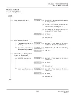
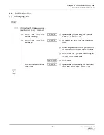
Страница 108: ...lephone set Dial Tone is not returned The station telephone set is DTMF type 1 System Data Programming for the station CM05 Y 0 CM10 Y 00 CM12 Y 00 System does not receive any digits dialed by the sta...

Страница 109: ...elephone set 1 2 LC blade Telephone set The call is routed to a station other than the dialed number 1 2 System Data Programming for destination station Number CM05 Y 0 CM10 Y 00 Call Forwarding All C...

Страница 110: ...ramming for the trunk CM05 Y 0 CM10 Y 00 BUSY LED on the trunk blade is on 1 2 3 Disconnect the trunk from the line on the MDF If the LED goes out there is a problem with the Central Office Distant Of...

Страница 111: ...g off hook on the test telephone set check for trouble with wiring on the MDF and the trunk blade If not there is a problem with the distant office or the C O line 1 Trunk blade In case of ODT blade 1...

Страница 112: ...ipment or the line If not check for trouble with wiring on the MDF and the trunk blade Any dialed digit is not transmitted to the distant office 1 2 System Data Programming for the trunk route CM35 Y...

Страница 113: ...t disconnected 1 2 Appropriate signal DP DTMF to distant office is transmitted System Data Programming for DP signal CM35 Y 001 013 023 025 System Data Programming for DTMF signal CM35 Y 001 013 024 0...

Страница 114: ...st telephone set to the line on the MDF 3 4 If the telephone rings check for trouble with wiring on the MDF and the trunk blade If not there is a problem with the distant of fice or the line 1 Trunk b...

Страница 115: ...ODT blade 1 2 3 System Data Programming for the trunk CM35 Y 001 009 010 Disconnect trunk from the line on the MDF To perform a Loopback Test make a back to back connect of the trunk and another trun...

Страница 116: ...001 fm FAULT INFORMATION DISPLAY The Tie Line Incoming Call DID Call is routed to a different station other than the dialed station or to Reorder Tone 1 System Data Programming for the trunk CM35 Y 00...

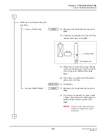
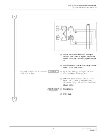
Страница 117: ...k from the line on the MDF To perform the Speech Path Test internally make the following connection on the MDF according to type of blade 3 4 If the trouble remains replace the trunk blade If not ther...

Страница 118: ...k if the failure reoccurs If the failure recurs there is a problem with the distant office If not replace the trunk blade 1 2 Trunk blade CPU blade Transmission quality is not accept able Noise Distor...

Страница 119: ...8300R3 software required Preassigned stations are not con nected to the C O line when system alarm or power failure has occurred 1 Between the Station and the BRI COT blade is properly connected 1 BRI...

Страница 120: ...ne Terminal station CM05 Y 0 CM10 Y 00 CM11 CM12 CM13 CM90 Y 00 CM93 RUN LED on the CPU blade is flashing 1 2 3 Digital Multiline Terminal DLC blade CPU blade Speech Path Trouble No Connection One Way...

Страница 121: ...95ch2001 fm FAULT INFORMATION DISPLAY No Tone Ringer 1 2 System Data Programming for Digital Mul tiline Terminal Tone Ringer CM90 Y 01 Adjust Ringer Volume on Digital Multiline Terminal 1 Digital Mul...

Страница 122: ...tem Data Programming for the IP Sta tion and VoIPDB CM0B CM10 Y 01 CM11 CM12 CM13 CM90 Y 00 CM93 IP Station setup is properly completed by IP Station menu RUN LED on the CPU blade is flashing 1 2 3 IP...

Страница 123: ...cable connection by transmitting the ping packet to the VoIPDB from PC on the LAN LCD does not display any infor mation 1 Adjust Display contrast 1 2 IP Station VoIPDB No Tone Ringer 1 2 System Data...

Страница 124: ...or the console CM05 Y 0 CM10 Y 00 CM60 CM90 Y 00 RUN Lamp on the CPU blade is flashing 1 2 3 DESKCON DLC blade CPU blade Speech Path Trouble No Connection One Way Connection 1 2 3 Headset or Handset o...

Страница 125: ...h2001 fm FAULT INFORMATION DISPLAY DSS Console Fault Keys on the DSS Console are ineffective 1 2 DLC blade is properly mounted System Data Programming for DSS Console CM05 Y 0 CM10 Y 00 CM96 CM97 1 2...

Страница 126: ...2 58 NWA 033627 001 Rev 4 0 95ch2001 fm THIS PAGE LEFT BLANK INTENTIONALLY NOVEMBER 21 2008...

Отзывы: