background image

2-6      Setup and Operation

Minitower Setup

 Set up the minitower systems by making the following connections.

1. 

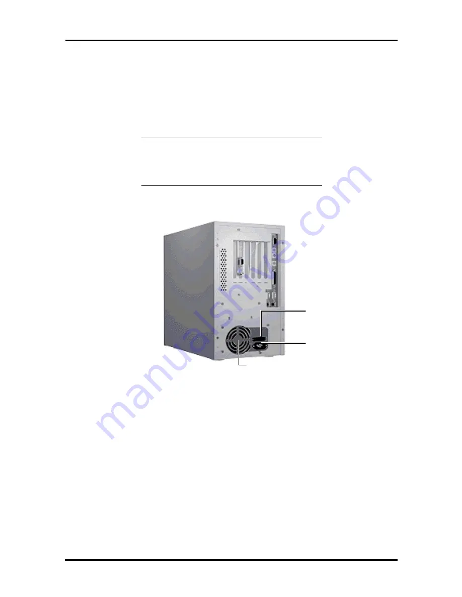
Set the voltage selector switch to 115V (U.S. and Canada) or 230V and plug the
power cord into the power socket (see Figure 2-7).

 NOTE:   The correct AC input voltage must be
properly set. Select the appropriate voltage with
the voltage selector switch located at the rear of
the system.


Figure 2-7   Minitower Voltage Selector Switch


Voltage Selector
Switch

System Power
Socket

Fan

Содержание POWERMATE

Страница 1: ...are warranted in accordance with the terms of the Warranty Statement accompanying each product However actual performance of each such product is dependent upon factors such as system configuration customer data and operator control Since implementation by customers of each product may vary the suitability of specific product configurations and applications must be determined by the customer and i...

Страница 2: ...1 Motion Video Controller 1 11 Graphics Accelerator 1 11 Video Memory 1 11 Interrupt Controller 1 12 I O Addressing 1 14 ISA Bus 1 15 PCI Local Bus 1 15 PCI Auto Configuration 1 15 PCI IDE Ports 1 15 Parallel Interface 1 16 Serial Interface 1 16 Infrared Interface 1 17 Power Supply 1 18 Diskette Drive 1 18 Hard Disk Drive 1 18 Keyboard 1 19 Mouse 1 19 Multimedia Components 1 19 Integrated Audio 1 ...

Страница 3: ...npacking and Repacking 2 1 Setup 2 1 Desktop Setup 2 1 Minitower Setup 2 6 CD ROM Reader 2 11 System Configuration 2 12 Setup Utility 2 12 How to Start Setup 2 13 How to Use Setup 2 14 Menu Bar 2 14 Legend Bar 2 15 Field Help Window 2 16 General Help Window 2 16 Main Menu Options 2 16 IDE Adapters 2 17 Memory Cache 2 19 Memory Shadow 2 19 Boot Options 2 20 Numlock 2 20 Advanced Menu 2 21 Integrate...

Страница 4: ...top Cover 3 3 Removing the Minitower Cover 3 5 Expansion Boards 3 6 Expansion Slot Locations 3 7 Expansion Board Installation 3 8 Inside Slot Expansion Board Installation 3 11 System Board Options 3 12 SIMM Upgrade 3 13 Checking System Memory 3 13 SIMM Removal 3 15 SIMM Installation 3 16 Video Upgrade 3 17 Processor Upgrade 3 18 Processor Removal 3 18 Processor Installation 3 19 MIDI Joystick Upgr...

Страница 5: ...alling a 3 1 2 Inch Drive into a Minitower Rear Slot 3 34 Removing the Minitower Front Panel 3 36 Installing the Minitower 5 1 4 Inch Device 3 38 Replacing the Minitower Front Panel 3 40 Adding External Options 3 41 Parallel Printer 3 41 RS 232C Device Connection 3 42 Section 4 Maintenance and Troubleshooting Maintenance 4 1 System Cleaning 4 2 Keyboard Cleaning 4 2 Mouse Cleaning 4 3 Troubleshoot...

Страница 6: ...moval 6 8 5 1 4 Inch Device Removal 6 9 Rear 3 1 2 Inch Drive Removal 6 11 Card Guide Fan Bracket Removal 6 12 Speaker Assembly Removal 6 13 Power Supply Removal 6 14 PCI ISA Backboard Removal 6 15 System Board Removal 6 15 Illustrated Parts Breakdown 6 17 Appendix A Connector Pin Assignments CD Audio Connector Pin Assignments A 3 Serial Interface Connectors A 3 Parallel Interface Connector A 4 VG...

Страница 7: ...GB Hard Disk Drive Jumper Settings C 6 Appendix D CD ROM Reader Specifications and Jumper Settings CD ROM Reader Specifications D 1 CD ROM Reader Connectors and Jumper Settings D 2 List of Figures 1 1 Desktop System Controls and Storage Device Slots 1 3 1 2 Minitower System Controls and Storage Device Slots 1 4 2 1 Desktop Voltage Selector Switch 2 2 2 2 Desktop Peripheral Connections 2 2 2 3 Desk...

Страница 8: ...ts and Connectors 3 12 3 14 Removing a SIMM 3 15 3 15 Inserting the SIMM 3 16 3 16 Aligning the Video DRAM Module with the Socket 3 17 3 17 Removing the Metal MIDI Joystick Punch Out in the Desktop 3 20 3 18 Removing the Metal MIDI Joystick Punch Out in the Minitower 3 21 3 19 Locating Device Slots in the Desktop 3 22 3 20 Locating Device Slots in the Minitower 3 22 3 21 System Board Cable Connect...

Страница 9: ... the Desktop 3 43 3 47 Connecting an RS 232C Cable to the Minitower 3 43 4 1 Removing the Mouse Ball Cover 4 3 4 2 Battery Socket Location 4 8 4 3 Battery Removal 4 9 4 4 RTC Chip Removal 4 9 5 1 System Unit Cover Screws 5 3 5 2 Removing the System Unit Cover 5 3 5 3 Expansion Slot Screw 5 4 5 4 Inside Expansion Slot Screw 5 4 5 5 PCI ISA Backboard Screws 5 5 5 6 3 1 2 Inch Drive Bracket 5 6 5 7 3...

Страница 10: ...ng the Device Rails 6 11 6 15 Removing the Drive Bracket Screws 6 11 6 16 Securing the Drive to the Bracket 6 12 6 17 Removing the Card Guide Fan Bracket Assembly 6 13 6 18 Speaker 6 13 6 19 Power Supply Screws 6 14 6 20 PCI ISA Backboard 6 15 6 21 System Board Removal 6 16 6 22 PowerMate V Minitower Illustrated Parts Breakdown 6 19 A 1 System Board Layout A 1 A 2 Detailed Front System Board Conne...

Страница 11: ...rameters 2 20 2 6 Numlock Parameters 2 20 2 7 Advanced Menu Parameters 2 21 2 8 Integrated Peripherals Parameters 2 22 2 9 System Security Options 2 23 2 10 Power Management Parameters 2 25 3 1 Recommended Memory Upgrade Path 3 14 4 1 NEC Service and Information Telephone Numbers 4 1 4 2 Problems and Solutions 4 4 5 1 PowerMate V Desktop Disassembly Sequence 5 1 5 2 PowerMate V Desktop Field Repla...

Страница 12: ...yboard and Mouse Connector Pin Assignments A 6 A 8 IRDA Connector Pin Assignments A 7 A 9 Suspend Connector Pin Assignments A 7 A 10 Fan Connector Pin Assignments A 7 A 11 Diskette Drive Connector Pin Assignments A 8 A 12 IDE Connector Pin Assignments A 9 A 13 SIMM Socket Pin Assignments A 10 A 14 ISA PCI Backboard Connector Pin Assignments A 11 A 15 ISA Expansion Slot Pin Assignments A 13 C 1 Har...

Страница 13: ...umbers that provide access to the NEC Bulletin Board System BBS FastFacts and Technical Information Bulletins Recommended maintenance information and solutions to possible problems that may occur are also provided Section 5 Desktop Repair provides desktop disassembly and reassembly procedures along with an illustrated parts breakdown NEC service and spare parts ordering information is also provide...

Страница 14: ...xvi Preface ...

Страница 15: ...DIP dual in line package DMA direct memory access DMAC DMA controller DOS disk operating system DRAM dynamic RAM ECC error checking and correction ECP enhanced capabilities port ECP EGA Enhanced Graphics Adapter EPP Enhanced Parallel Port EPROM erasable and programmable ROM EVGA Enhanced Video Graphics Array F Fahrenheit FAX facsimile transmission FCC Federal Communications Commission FG frame gro...

Страница 16: ... assistant PFP plastic flat package PIO parallel input output pixel picture element PROM programmable ROM RAM random access memory RAMDAC RAM digital to analog converter RGB red green blue RGBI red green blue intensity ROM read only memory rpm revolutions per minute R read RTC real time clock R W read write S slave SCSI Small Computer System Interface SG signal ground SIMM single inline memory mod...

Страница 17: ...nch diskette drive 540 MB hard disk with 8 MB of RAM or 1 2 GB hard disk with 16 MB of RAM 3 1 2 inch diskette drive 540 MB hard disk with 8 MB of RAM or 1 2 GB hard disk with 16 MB of RAM 3 1 2 inch diskette drive 540 MB hard disk with 8 MB of RAM or 1 2 GB hard disk with 16 MB of RAM Network ready system 3 1 2 inch diskette drive 1 2 GB hard disk Network board 8 MB of RAM 3 1 2 inch diskette dri...

Страница 18: ... diskette drive 850 MB hard disk Network board 8 MB of RAM Multimedia 3 1 2 inch diskette drive 1 6 GB hard disk six speed CD ROM reader System board w audio 16 MB of RAM 7 W Speakers Microphone 3 1 2 inch diskette drive 1 6 GB hard disk six speed CD ROM reader System board w audio 16 MB of RAM 7 W Speakers Microphone 3 1 2 inch diskette drive 1 6 GB hard disk six speed CD ROM reader System board ...

Страница 19: ...inch storage devices The non multimedia hard disk systems ship with an accessible 3 1 2 inch diskette drive and an internal 3 1 2 inch hard disk drive leaving two accessible 5 1 4 inch storage device slots available for optional devices The multimedia systems ship with an accessible 3 1 2 inch diskette drive an internal 3 1 2 inch hard disk drive and an accessible 5 1 4 inch CD ROM reader leaving ...

Страница 20: ...s with the system The bracket attaches to the inside rear of the system The non multimedia hard disk systems ship with an accessible 3 1 2 inch diskette drive and an internal 3 1 2 inch hard disk drive leaving three accessible 5 1 4 inch storage device slots and two internal slots available for optional devices The multimedia systems ship with an accessible 3 1 2 inch diskette drive an internal 3 ...

Страница 21: ...integrated input output I O controller with keyboard diskette drive and hard disk drive controllers Supports two serial ports a parallel port and an IrDA port PCI local bus for fast data transfer support for Intel OverDrive processors 8 MB RAM 16 MB in multimedia configurations 1 2 GB and 1 6 GB hard disk configurations ships with 32 bit non parity 70 ns single inline memory modules SIMMs RAM expa...

Страница 22: ...e mode when idle for a specified amount of time 3 1 2 inch 1 44 MB diskette drive standard all configurations PCI ISA backboard configurations desktop provides four expansion slots two ISA one PCI and one shared ISA PCI connectors minitower provides five expansion slots three ISA one PCI and one shared ISA PCI connectors external connectors for connecting the following external devices VGA compati...

Страница 23: ...Triton 82430FX PCI ISA Chip Set 82437FX 82438FX 824371FB System controller Data path unit PCI ISA IDE accelerator bridge chip SMC FDC37C935 or 665 Integrated Plug and Play Ultra I O controller Alliance ProMotion 6422 PCI GUI graphics controller 28F001 128k x 8 Flash ROM Dallas DS12887 MC146818 or Toshiba CR2032 Coin Cell Battery Real time clock battery SMC 665 or 3 Volt Lithium CMOS battery SMC 93...

Страница 24: ...system board contains 256 KB of secondary cache external to the processor The first release shipped uses 15 ns asynchronous SRAM PowerMate V90 and V100 or 20 ns asynchronous SRAM PowerMate V75 cache The second release of the PowerMate V series ships with 15 ns synchronous pipe line burst cache Cache allows data to be sent or received from cache with one wait state burst Cache memory improves read ...

Страница 25: ...come standard with 8 MB of memory 640 KB of base memory and 7 MB of extended memory All multimedia 1 2 GB and 1 6 GB hard disk configurations come standard with 16 MB of memory 640 KB of base memory and 15 MB of extended memory System memory can be expanded up to 128 MB using optional single in line memory modules SIMMs installed in SIMM sockets on the system board Four SIMM sockets are integrated...

Страница 26: ...ays be filled for the system to operate Table 1 5 shows the SIMM memory upgrade path Table 1 5 SIMM Memory Upgrade Path Total Memory SIMM 1 SIMM 2 SIMM 3 SIMM 4 8 MB 4 MB 4 MB Empty Empty 16 MB 4 MB 4 MB 4 MB 4 MB 16 MB 8 MB 8 MB Empty Empty 24 MB 4 MB 4 MB 8 MB 8 MB 24 MB 8 MB 8 MB 4 MB 4 MB 32 MB 8 MB 8 MB 8 MB 8 MB 32 MB 16 MB 16 MB Empty Empty 40 MB 4 MB 4 MB 16 MB 16 MB 40 MB 16 MB 16 MB 4 MB...

Страница 27: ...0 frames per second fps Support includes MPEG 1 and Video for Windows MPEG is a compression decompression standard developed by the Motion Picture Experts Group MPEG produces full screen 30 fps broadcast quality digital video The video controller architecture maximizes the motion video performance and removes bandwidth bottlenecks to display multimedia data at its full speed Graphics Accelerator T...

Страница 28: ... rates 1600 by 1200 pixels 16 256 colors 60 Hz and 70 Hz 1280 by 1024 pixels 256 colors 60 Hz 72 Hz and 75 Hz 1024 by 768 pixels 64K colors 60 Hz 66 Hz 70 Hz 72 Hz and 75 Hz 800 by 600 pixels 16 8 million colors 56 Hz 60 Hz 72 Hz and 75 Hz Interrupt Controller The interrupt controller operates as an interrupt manager for the entire AT system environment The controller accepts requests from periphe...

Страница 29: ...ssignments Interrupt Priority Interrupt Device IRQ00 Counter Timer IRQ01 Keyboard IRQ02 Cascade INT output from slave IRQ03 COM2 and COM4 IRQ04 COM1 and COM3 IRQ05 Parallel Port 2 Audio if present IRQ06 Diskette Drive Controller IRQ07 Parallel Port 1 IRQ08 Real time clock IRQ09 Available IRQ10 Available IRQ11 Available IRQ12 PS 2 mouse IRQ13 Coprocessor IRQ14 Primary IDE IRQ15 Secondary IDE Networ...

Страница 30: ...ge registers 00A0 00A1 Interrupt controller 2 00C 00DE DMA controller 2 00E0 00EF Reserved 00F0 Clear math coprocessor error 00F1 Reset math coprocessor 0F8 0FF Math coprocessor 170 177 Secondary hard disk controller 1F0 1F7 Primary hard disk controller 200 207 Game I O 220 22F Sound port 238 23F Serial port 4 used for remapping 278 27F Parallel port 2 2B0 2DF Alternate EGA adapter 2F8 2FF Serial ...

Страница 31: ...um performance at high clock speeds and provides a clear upgrade path to future technologies The PCI bus contains two embedded PCI devices the PCI local bus IDE interface and the PCI video graphics controller PCI expansion slot connector pin assignments are provided in Appendix A PCI Auto Configuration The system comes with a PCI auto configuration utility that operates in conjunction with the sys...

Страница 32: ...esses are 3BCh 378h and 278h I O addresses and interrupts for the parallel port are given in Table 1 8 NOTE Any interrupts used for the built in parallel port are not available for ISA parallel ports Table 1 8 Parallel Port Addressing and Interrupts Starting I O Address Interrupt Level Port 378 IRQ05 LPT1 278 IRQ05 LPT1 or LPT2 3BC IRQ05 LPT1 or LPT2 378 IRQ07 LPT1 278 IRQ07 LPT1 or LPT2 3BC IRQ07...

Страница 33: ...to Standard for serial port transfers See Section 2 Setup and Operation for information on resetting the port through Setup Serial interface specifications include Baud rate up to 19 2 KB per second Word length 5 6 7 or 8 bits Stop bit 1 1 5 or 2 bits Start bit 1 bit Parity bit 1 bit odd parity or even parity Serial interface signals are output through the system board s 9 pin D subconnector The c...

Страница 34: ... into the system board Typically both diskette drives are terminated Connector locations are given in Appendix A HARD DISK DRIVE Up to two IDE hard drives are supported in the desktop system and up to four IDE hard drives in the minitower system The system board has two IDE PCI interface connectors primary and secondary for connecting various storage devices such as hard disk drives Each connector...

Страница 35: ...et and a microphone The following briefly describes each Information on setting up and operating the speakers microphone and CD ROM reader is in Section 2 Setup and Operation Integrated Audio Multimedia systems come with audio components integrated on the system board Non multimedia systems do not have the audio components on the system board The audio components include an OPTi 82C930 Sound Blast...

Страница 36: ...he back of the system Microphone The microphone that comes with the multimedia systems allows recording of voice and sound into computer data files The microphone connects to the MIC jack located on the back of the system The microphone works in conjunction with the audio software shipped with the system NETWORK BOARD Network ready systems are configured with an Ethernet network interface board NI...

Страница 37: ...e Power management can also be disabled Both can be set through Setup DESKTOP MANAGEMENT INTERFACE The Desktop Management Interface DMI is the standard interface used to manage system components on the computer DMI acts as a layer of abstraction between management applications and managed components such as systems network cards and printers With DMI a management application such as Hewlett Packar...

Страница 38: ...IF attributes and their respective values The Browser has the ability to set attributes and manage DMI components The NEC Browser can only accesses the local MIF database The Browser lets you access MIF attributes according to the structure defined by the DMTF It is not intended to be a general PC management application If a more comprehensive management application is desired use a product such a...

Страница 39: ...o switch to Detailed View screen Print to print DMI Browser Information to display program information version number and copyright Help to display help information for clicked toolbar buttons and menus Upon exiting the Browser the program saves the current viewing configuration The next time you use the Browser it restores all the viewing screens to the last known position Usage To start the NEC ...

Страница 40: ...n using the NEC DMI Browser here are a few suggestions on how to clear up the problem Reboot the system after installation otherwise you may have problems running the NEC DMI Browser If the product name serial number system boot time or other attribute returns a N A check the following Look at the AUTOEXEC BAT file to see if the line DMIDIR WIN16 BIN NECDMI EXE is present Make sure the file NECDMI...

Страница 41: ...tower One 3 1 2 inch front access slot One 3 1 2 inch internal slot three in the minitower Expansion Slots Four slots in the desktop five in the minitower two 16 bit ISA slots three in the minitower one ISA PCI shared slot one PCI slot two in the minitower Peripheral Interface PS 2 style keyboard connector rear panel PS 2 style mouse connector rear panel Two RS 232C serial ports rear panel Paralle...

Страница 42: ...switch selectable minitower CD ROM Reader Multimedia systems only See Appendix D for more specifications Quadruple speed Disc format ISO 9660 Data transfer rate 600 KB sec mode 1 684 4 KB sec mode 2 Access time typical 230 msec Built in buffer 128 KB Host interface IDE ATAPI Six speed Disc format ISO 9660 Data transfer rate 900 KB sec mode 11 11 MB sec mode 3 Access time typical 160 msec Built in ...

Страница 43: ...on off button power lamp Volume treble and bass control Mini stereo headphone jack Built in Stereo amplifier Subwoofer output jack 12 volt 120 AC power adapter Network Interface Board Network ready systems only 3Com EtherLink III 3C509B COMBO Network interface IEEE 802 31 10Base T and Ethernet IEEE 802 3 industry standard for 10 Mbps CSMA CD local area network Connectors RJ 45 AUI BNC Recommended ...

Страница 44: ...The carton contents for multimedia configurations include the system unit with a CD ROM player keyboard mouse speakers power cord user documentation CD ROM disc with hotload backup and system recovery diskette Repack the system using the original shipping carton and packing material Part numbers for replacement shipping cartons and packing material are included in Section 4 Illustrated Parts Break...

Страница 45: ...keyboard mouse monitor and printer cables to the back of the system unit see Figure 2 2 Figure 2 2 Desktop Peripheral Connections Fan System Power Socket Voltage Selector Switch Mouse Port Keyboard Port Audio Connectors VGA Monitor Connector Printer Port Serial Port 1 Serial Port 2 ...

Страница 46: ...ers as follows Locate the right speaker has the controls on the front and the speaker cable attached to the back Locate the left speaker and the speaker cable attached to the back Connect the right speaker cable to the left speaker cable Connect the speaker input cable to the right speaker and to the line out jack on the back of the system Connect the AC adapter to the right speaker and to a surge...

Страница 47: ...lide the microphone cable and microphone into the holder Adjust the microphone by pivoting it up and down and side to side Figure 2 4 Assembling the Microphone Holder Plug the microphone into the microphone in jack at the rear of the system see Figure 2 5 Figure 2 5 Connecting the Microphone Microphone Holder Microphone Cable Microphone Stand Microphone Line In Jack Line Out Jack Microphone In Jac...

Страница 48: ... system settings have changed run Setup see System Configuration later in this section Figure 2 6 Desktop Power Button Lamps and Suspend Button 7 Press the suspend button see Figure 2 6 to place the unit in the maximum power saving mode A blinking power lamp indicates that the system is in the power saving mode Pressing a key or moving the mouse places the system back in the Full Power mode If the...

Страница 49: ...h to 115V U S and Canada or 230V and plug the power cord into the power socket see Figure 2 7 NOTE The correct AC input voltage must be properly set Select the appropriate voltage with the voltage selector switch located at the rear of the system Figure 2 7 Minitower Voltage Selector Switch Voltage Selector Switch System Power Socket Fan ...

Страница 50: ...s 3 If setting up a network ready system connect the appropriate network cable to the network board at the rear of the system see Figure 2 9 Figure 2 9 Minitower Network Board Connections VGA Monitor Connector Audio Connectors Printer Port Serial Port 1 Serial Port 2 Keyboard Port Mouse Port RJ 45 Connector AUI Thick Ethernet Connector BNC Thin Ethernet Connector ...

Страница 51: ...the back of the system Connect the AC adapter to the right speaker and to a surge protector or wall outlet Press the power switch The power lamp lights Adjust the volume control as required 5 Assemble and connect the microphone multimedia systems only as follows Slide the microphone holder into the slot in the microphone stand as far as it will go see Figure 2 10 Slide the microphone cable and mic...

Страница 52: ...power lamp lights green indicating that the system is in Full Power mode The system automatically goes into its Power On Self Test POST and checks system components One beep indicates that the system has successfully completed its power on test If a problem occurs a series of beeps may sound If this happens repeatedly after powering on power off the system and Troubleshoot Microphone In Jack Line ...

Страница 53: ...e Figure 2 12 to place the unit in the power management mode The power lamp lights amber indicating that the system is in the power saving Suspend mode Pressing the Suspend button places the system back in the Full Power mode If the system is left alone for a preset time it goes into the automatic Standby mode The screen goes blank and the system goes into the power saving mode of operation Moving...

Страница 54: ...a stereo mini jack plug volume control for adjusting the headphone volume busy lamp that lights during read operations open close stop button for opening or closing the CD tray when the power is on When playing a CD press the open close stop button to stop the CD play skip button to play a loaded CD Press again to skip a selection This button is not available on all CD ROM readers CD tray that ope...

Страница 55: ...ormation is stored in nonvolatile memory Nonvolatile memory in the system is a complementary metal oxide semiconductor CMOS chip backed by a battery either a coin type battery or a real time clock battery module on the system board The battery supplies continuous power to the CMOS memory and maintains configuration information when system power is off Setup Utility The Setup utility is used to vie...

Страница 56: ...window appears similar to the following screen NOTE The screen shown is typical of the system The actual items on the Main Menu depend upon the hardware installed in the system Main Menu PhoenixBIOS Setup Copyright 1992 96 Phoenix Technologies Ltd Main Advanced Security Power Boot Exit System Time 10 19 20 Item Specific Help System Date 02 12 1996 Diskette A 1 44 MB 3 Tab Shift Tab or Diskette B N...

Страница 57: ...des a summary of command keys for using Setup The General Help window a window that appears any time during Setup after pressing F1 or Alt H This help window provides two pages of general information about using Setup The following subsections describe how to use the Main Menu window to set system parameters Menu Bar The menu bar at the top of the Main Menu window lists these menus Main Use this m...

Страница 58: ...sted in the legend bar on the bottom of the Setup menu to make the selections or exit the current menu Table 2 1 describes the legend keys and their alternates Table 2 1 Setup Key Functions Key Function F1 or Alt H Displays General Help window described later in this section Esc Exits the menu or arrow keys Selects a different menu or arrow keys Moves cursor up and down Tab or Shift Tab Cycles cur...

Страница 59: ...t for the currently selected Setup option It updates as the cursor is moved to each new field General Help Window Pressing F1 or Alt H on any menu brings up the General Help window that describes the legend keys and their alternates The scroll bar on the right of any window indicates that there is more than one page of information in the window Use Page Up and Page Down to display all the pages Pr...

Страница 60: ...ptions Selects the default boot options System Memory Automatically detected by the system Displays the amount of conventional memory detected at power on Extended Memory Automatically detected by the system Displays the amount of extended memory detected at power on IDE Adapters IDE adapters control the IDE devices such as IDE hard disk drives and IDE CD ROM readers in the system The system uses ...

Страница 61: ... displays an IDE adapters advanced features menu with IDE hard disk parameters Select an IDE Adapter option and set parameters for each hard disk separately Use Table 2 3 to configure the hard disk If the IDE hard disk features auto IDE type detection select the Autotype Fixed Disk parameter The system then automatically detects the hard disk type and sets the remaining parameters CAUTION Incorrec...

Страница 62: ...st compatible Fast PIO programmed input output is the slowest of the three enhanced modes Fast PIO3 is the fastest of the enhanced modes Memory Cache For memory caching parameters select Memory Cache directly from the Main Menu summary window See Table 2 4 for a description of memory cache parameters CAUTION Incorrect settings can cause the system to malfunction Table 2 4 Memory Cache Parameters P...

Страница 63: ...es the Previous Boot Incomplete message appears and the system boots with default settings The default setting 3 give the user three tries to boot the system before the Previous Boot Incomplete message appears Numlock Select Numlock directly from the Main Menu summary window to display the Keyboard Features menu Use the legend keys to make the selections and exit to the Main Menu Use Table 2 6 to ...

Страница 64: ...arameter resets automatically to No to reboot ISA Graphics Device Installed No default Yes Set to Yes if other system devices need to know if an ISA graphics device is installed Big Memory Mode Normal default Alternate Selects the method the BIOS uses to report memory sizes over 64 MB to the operating system Select Normal for MS DOS and Windows Select Alternate for OS 2 and Windows NT Large Disk A...

Страница 65: ... and interrupt request for the LPT port Auto selects the next available combination LPT Mode Output only default Bi directional ECP Enables parallel port to function normally Output only bidirectional or in an enhanced capabilities port ECP mode Check the printer documentation to set the correct LPT mode for your printer ECP Channel DMA 0 DMA 1 DMA 3 Available when ECP is selected for the LPT mode...

Страница 66: ... User Password on the menu displays a Set Password dialog box with the following prompts Enter new password Re enter new password To set a password type the password and press Enter Reenter the password and press Enter See Table 2 9 for a description of the security features Use the legend keys to make the selections and exit to the Main Menu Table 2 9 System Security Options Feature Options Descr...

Страница 67: ...ected Write protected helps prevent viruses When write protected operating systems and viruses and application programs which attempt to modify the boot sector will not be able to do so System Backup Reminder and Virus Check Reminder Disabled default Daily Weekly Monthly When a schedule is specified displays a message during bootup asking Y N if the system has been backed up or scanned for viruses...

Страница 68: ...agement options with predefined values Select Customize to make customize selections Disabled turns off all power management Sleep Timeout 15 min default Disabled User Selectable Inactivity period required before partial power shutdown Standby mode Deep Sleep Timeout 15 minute default Disabled User Selectable Inactivity period required before Sleep timeout to maximum power shutdown Suspend mode Vi...

Страница 69: ... them operative Unlike standard RAM memory NVRAM is sustained by an onboard battery and stays on when the system is turned off After saving the selections the program displays this message NOTICE Changes have been saved continue If an attempt is made to exit without saving Setup asks if the changes should be saved before exiting During bootup Setup attempts to load the values saved in NVRAM If the...

Страница 70: ...Values During a Setup session if a mistake has been made and has not yet been saved to NVRAM the previously saved NVRAM values can be restored Selecting Load Previous Values on the Exit menu updates all the selections and displays this message NOTICE Previous values have been loaded continue Save Changes Save Changes saves all the selections without exiting Setup Other menus selections can be revi...

Страница 71: ...s and click OK when done Baud rate select a baud rate that matches the modem Parity none Data bits 8 Stop bits 1 Flow control Xon Xoff select Hardware if using 14 4 bps or higher 3 From the Phone menu click on Dial enter the BBS phone number 508 635 4706 and click OK Your business phone or location might require a 9 1 or 1 prefix 4 Press Enter twice 5 Enter your first name last name and password P...

Страница 72: ...S Update Utility Update the BIOS from the BIOS flash diskette as follows 1 Write down the Setup parameters currently set on the system 2 Turn off the system 3 Insert the flash diskette in drive A and turn on the system 4 The update procedes automatically and shows a BIOS Update successfully completed message when done 5 Press any key to reboot the system 6 Remove the flash diskette ...

Страница 73: ...d minitower covers are included in this section GENERAL RULES FOR INSTALLING OPTIONS Follow these general rules when installing system options Turn off system power and unplug the power cable Turn off and disconnect all peripherals When handling boards or chips touch the system unit frame to discharge static Do not disassemble parts other than those specified in the procedure All screws are Philli...

Страница 74: ...s a board or chip in its anti static packaging until ready to install it Dissipate static electricity before handling any system components boards chips and so on by touching a grounded metal object such as the system s unpainted metal chassis If possible use anti static devices such as wrist straps and floor mats Always hold a chip or board by its edges Avoid touching the components on the chip o...

Страница 75: ...er is removed only when the power cable is unplugged 1 Turn off and unplug the system unit 2 Disconnect the keyboard mouse monitor and any other external options such as a printer from the rear of the system unit CAUTION Electrostatic discharge can damage computer components Discharge static electricity by touching a metal object before removing the system unit cover 3 Remove the two cover screws ...

Страница 76: ...er to release it from the front panel Also press against the rear panel to slide the cover one inch away from the front panel Figure 3 2 Releasing the Desktop Cover 5 Lift the cover up and away from the system unit 6 Reinstall the cover by reversing steps 1 through 5 above Be sure that the cover tabs on the sides of the cover align inside the frame of the unit when positioning the cover over the c...

Страница 77: ...g the system unit 2 Disconnect the keyboard mouse monitor and any other device such as a printer connected from the rear of the system CAUTION Electrostatic discharge can damage computer components Discharge static electricity by touching a metal object before you remove the system unit cover 3 Remove the four cover screws from the rear of the system unit see Figure 3 3 Figure 3 3 Removing Minitow...

Страница 78: ... cover by reversing steps 1 through 5 above Be sure that the cover tabs on the sides of the cover align inside the frame of the unit when replacing the cover EXPANSION BOARDS The computer supports ISA Plug and Play expansion boards Plug and Play expansion boards allow installing a board in an expansion slot without changing the hardware settings There are no system resource conflicts to resolve Pl...

Страница 79: ...t in each system ISA expansion slots support industry standard 8 bit or 16 bit expansion boards The PCI ISA slot also supports PCI expansion boards PCI expansion boards run at the system s processor speed The PCI bus handles 32 bits of data at a time being wider as well as faster than the standard ISA bus PCI boards can send and receive data much faster which boosts system performance Figure 3 5 L...

Страница 80: ...s or jumpers on the board 3 If installing a board in the inside expansion slot next to the power supply in the desktop system see Inside Slot Expansion Board Installation Otherwise continue to the next step 4 Remove the screw securing an expansion slot cover and remove the cover see Figure 3 7 or Figure 3 8 Save the screw for installing the expansion board Save the slot cover for future use ISA Sl...

Страница 81: ...screw If the slot cover does fall into the unit remove it before replacing the cover Figure 3 7 Removing a Slot Cover in the Desktop Figure 3 8 Removing a Slot Cover in the Minitower 5 Hold the board by its edges and insert it into the expansion slot see Figure 3 9 or Figure 3 10 Align full size expansion boards with the guide rail at the front of the system unit Slot Cover Slot Cover ...

Страница 82: ...e to side to seat it into the connector 6 Insert the screw removed earlier to secure the expansion board to the support bracket Figure 3 10 Inserting the Board in the Minitower 7 Attach any signal cables required by the expansion board 8 Replace the system unit cover Figure 3 9 Inserting the Board in the Desktop ...

Страница 83: ...slot cover support and expansion slot cover to the rear of the system see Figure 3 11 Remove the slot cover support and slot cover from inside the system unit CAUTION Take care not to drop the slot cover and support into the system Figure 3 11 Removing the Slot Cover Support Screws 4 Hold the board by its edges component side down and the bracket end facing the rear of the unit and insert it into ...

Страница 84: ...ach any signal cables required by the expansion board 7 Replace the system unit cover SYSTEM BOARD OPTIONS SIMM video and processor upgrades require locating the connector on the system board See the following figure for connector locations Figure 3 13 System Board Upgrade Sockets and Connectors Screws Expansion Board Bracket Slot Cover Support Video DRAM Sockets Processor Socket Audio Wave Connec...

Страница 85: ...corrosion between different metals only use tin plated SIMM sticks Checking System Memory Use the following procedure to check the memory installed in the system determine the SIMM configuration needed to increase memory locate the sockets for SIMM installation 1 Locate the four SIMM sockets on the system board see Figure 3 13 If any cables block access to the SIMM sockets label and disconnect the...

Страница 86: ... 32 MB 16 MB 16 MB Empty Empty 40 MB 4 MB 4 MB 16 MB 16 MB 40 MB 16 MB 16 MB 4 MB 4 MB 48 MB 8 MB 8 MB 16 MB 16 MB 48 MB 16 MB 16 MB 8 MB 8 MB 64 MB 16 MB 16 MB 16 MB 16 MB 64 MB 32 MB 32 MB Empty Empty 72 MB 4 MB 4 MB 32 MB 32 MB 72 MB 32 MB 32 MB 4 MB 4 MB 80 MB 8 MB 8 MB 32 MB 32 MB 80 MB 32 MB 32 MB 8 MB 8 MB 96 MB 16 MB 16 MB 32 MB 32 MB 96 MB 32 MB 32 MB 16 MB 16 MB 128 MB 32 MB 32 MB 32 MB ...

Страница 87: ...Remove the system unit cover as previously described 2 Locate the SIMM sockets see Figure 3 13 3 Press the metal clips at the outer edges of the socket away from the SIMM 4 Push the SIMM away from the locking tabs and remove it from the socket see Figure 3 14 Figure 3 14 Removing a SIMM 5 Install a SIMM per the following procedure Clips ...

Страница 88: ...discharge by touching the system s metal chassis 3 Position the SIMM in the socket The notched end of the SIMM allows only the correct positioning 4 Insert the SIMM at an angle into the socket 5 Tilt the SIMM towards the locking tabs using equal pressure at the ends of the SIMM until it locks into the socket see Figure 3 15 Figure 3 15 Inserting the SIMM 6 Replace any cables or boards that may hav...

Страница 89: ...ur view of the sockets remove the boards see Expansion Board Removal CAUTION Reduce static discharge by touching the system s metal chassis 3 Align the notched ends of the module and socket see Figure 3 16 Using equal pressure gently press the module into the socket Repeat for the second module Figure 3 16 Aligning the Video DRAM Module with the Socket 4 Replace any boards that were removed 5 Repl...

Страница 90: ...move the processor currently installed in the system then install the upgrade processor Processor Removal Remove the installed processor on the system board as follows 1 Remove the system unit cover as previously described 2 Locate the processor socket see Figure 3 13 If any expansion boards are obstructing the socket remove the boards 3 Release the heatsink clip from the tabs on the socket 4 Rele...

Страница 91: ...y installed processor requires a system board jumper change see Appendix B System Board Jumpers 5 Replace any boards removed during this procedure 6 Replace the system unit cover MIDI JOYSTICK UPGRADE The system comes with a MIDI joystick connector on the system board Installing the optional MIDI joystick kit provides an MIDI joystick connector at the rear of the system Install the optional MIDI j...

Страница 92: ... pulling the metal plate back and forth until it releases see Figure 3 17 or Figure 3 18 6 Insert the other end of the MIDI joystick cable into the punch out in the rear panel from inside 7 Secure the cable with the two screws provided with the kit 8 Replace any boards that were removed during this procedure 9 Replace the system unit cover Figure 3 17 Removing the Metal MIDI Joystick Punch Out in ...

Страница 93: ... four storage device slots and the minitower has seven slots a 3 1 2 inch accessible device slot which contains the standard 1 44 MB diskette drive internal hard disk drive slots 1 inch high thin height desktop one 3 1 2 inch internal hard disk drive slot minitower three 3 1 2 inch internal hard disk drive slots Hard disk configurations come with an IDE hard disk installed accessible device slots ...

Страница 94: ...s Figure 3 19 Locating Device Slots in the Desktop Figure 3 20 Locating Device Slots in the Minitower 3 1 2 Inch Internal Slot contains hard disk in hard disk configurations 3 1 2 Inch Slot contains 1 44 MB diskette drive 5 1 4 Inch Accessible Slots Top 5 1 4 inch slot is available in some configurations 3 1 2 Inch Internal Slot contains hard disk in hard disk configurations 3 1 2 Inch Slot contai...

Страница 95: ...must be set correctly as the first master or second slave device on the IDE channel The standard IDE hard disk in hard disk models is set as the master device on the primary IDE connector The CD ROM reader in multimedia models is the master device on the secondary IDE connector Device Cables The cables used for installation of optional storage devices include diskette drive signal cable IDE signal...

Страница 96: ...e 3 22 shows a three connector diskette drive signal cable Figure 3 22 Optional Diskette Drive Signal Connector IDE Signal Cables Hard disk systems come with a three connector IDE interface cable attached to the primary IDE connector Multimedia systems come with a second IDE cable connected to the CD ROM reader and to the secondary IDE connector Each IDE connector on the system board supports two ...

Страница 97: ...wer cables come from the power supply and are attached to the standard storage devices System power cables vary in length and provide connector sizes to accommodate a variety of supported storage configurations Power cable connectors are keyed to fit only in the correct position Figure 3 24 shows the power cable connectors Figure 3 24 Power Cable Connectors Connects to IDE Devices Connects to Syst...

Страница 98: ... connector on the IDE device Take care to prevent bending drive connector pins Align the IDE cable connector as shown in Figure 3 25 2 Locate an available power connector coming from the power supply 3 Connect the appropriate power cable to the power connector on the IDE device Figure 3 25 Connecting IDE Device Cables 4 If installing an IDE CD ROM reader also connect the audio cable see the instru...

Страница 99: ...ting 1 2 MB Diskette Drive Cables Desktop Storage Device Installation The following subsections describe how to install 3 1 2 inch and 5 1 4 inch drives The installation procedures include removing the desktop 3 1 2 inch drive bracket installing a desktop 3 1 2 inch drive removing the desktop front panel installing a desktop 5 1 4 inch device replacing the desktop front panel replacing the desktop...

Страница 100: ... top of the power supply Figure 3 27 Removing the 3 1 2 Inch Drive Bracket Installing the Desktop 3 1 2 Inch Drive Install a hard disk drive into the desktop drive bracket as follows 1 Remove the system unit cover as previously described 2 Remove the 3 1 2 inch drive bracket from the system unit see Removing the Desktop 3 1 2 Inch Drive Bracket 3 Follow the preinstallation instructions that come w...

Страница 101: ...he Desktop 3 1 2 Inch Drive Bracket Removing the Desktop Front Panel Remove the desktop front panel only if installing a 5 1 4 inch device The front panel does not need to be removed if installing a 3 1 2 inch hard disk drive If installing a 3 1 2 inch hard disk drive see Installing the Desktop 3 1 2 Inch Drive 1 Remove the system unit cover as previously described 2 Remove the front panel by rele...

Страница 102: ...ed slot by pressing the panel tabs from inside the front panel and pushing the blank panel out see Figure 3 30 Figure 3 30 Locating the Blank Panel Tabs 5 Remove the perforated metal plate from the selected slot on the chassis by pulling the metal plate back and forth until it releases 6 Install the device see Installing the Desktop 5 1 4 Inch Device Top Blank Panel Tabs Bottom Blank Panel Tabs ...

Страница 103: ...vice such as setting jumpers and switches NOTE If the device comes with rails do not attach them Remove any rails already attached 4 From the front of the system insert the device connector end first into the device slot NOTE To easily access device connectors for cabling do not insert a 5 1 4 inch device all the way into the slot 5 Connect the device cables 6 Align the holes in the device with th...

Страница 104: ...m unit 2 Evenly press the front panel into position until the tabs lock the panel in place see Figure 3 32 Tabs behind panel Front Panel Blank Panel Figure 3 32 Aligning the Desktop Front Panel 3 Continue to Step 5 in Replacing the Desktop 3 1 2 Inch Drive Bracket Replacing the Desktop 3 1 2 Inch Drive Bracket When replacing the 3 1 2 inch drive bracket take care to prevent pulling and loosening t...

Страница 105: ...diskette drive was installed remove the protective cardboard insert from the drive 6 Run the Setup program to set the new configuration Minitower Storage Device Installation The following subsections describe how to install 3 1 2 inch and 5 1 4 inch drives The installation procedures include installing a 3 1 2 inch drive in the minitower internal front slot installing a 3 1 2 inch drive in the min...

Страница 106: ...n the drive with the holes in the device cage and secure the cage with four screws two to a side see Figure 3 34 5 Replace the system unit cover 6 Run the Setup program to set the new configuration Figure 3 34 Left Side Drive Screws Installing a 3 1 2 Inch Drive into a Minitower Rear Slot Install a second 3 1 2 inch hard disk drive into the system as follows NOTE Adding a second hard disk to hard ...

Страница 107: ...m see Figure 3 35 Figure 3 35 Removing the Drive Bracket Screws 5 Insert the first drive into the lower slot of the 3 1 2 inch drive bracket Insert the drive connectors so that the connectors face toward the center of the system unit 6 Align the holes in the drive with the holes in the bracket 7 Secure the drive to the bracket with the four screws two to a side that come with the drive see Figure ...

Страница 108: ...ice The front panel does not need to be removed if installing a 3 1 2 inch hard disk drive If installing a 3 1 2 inch hard disk drive see Installing the 3 1 2 Inch Drive into the Minitower Front Slot or Installing the 3 1 2 Inch Drive into a Minitower Rear Slot 1 Remove the minitower system unit cover as previously described 2 The front panel is secured with six metal clips see Figure 3 37 Remove ...

Страница 109: ...3 38 Figure 3 38 Locating the Blank Panel Tabs 6 Remove the slot cover from the selected slot by removing the two slot cover screws on the front of the system see Figure 3 39 Figure 3 39 Locating the Slot Cover 7 Install the minitower 5 1 4 inch device see Installing the Minitower 5 1 4 Inch Device Front Panel inside view Blank Panel Tabs Slot Covers Multimedia systems come with a CD ROM reader in...

Страница 110: ...top 5 1 4 inch slot do not attach the device rails that came with the system The rails must be used when installing a device in the middle and bottom 5 1 4 inch device slots 3 If installing the device into the top 5 1 4 inch slot go to Step 4 Otherwise locate the device rails that ship with the system Attach the rails to the sides of the device with the four screws that come with the device see Fi...

Страница 111: ...the device with the four screws that come with the device two to a side see Figure 3 41 and Figure 3 42 If installing a device with rails in the middle or bottom 5 1 4 inch slot secure the device with the two screws that were removed during slot cover removal see Removing the Minitower Front Panel and Figure 3 41 Figure 3 41 Front and Left Side Device Screws Figure 3 42 Right Side Device Screws Tw...

Страница 112: ...he minitower front panel only after it has been removed in a 5 1 4 inch device installation 1 Route the LED and IR cables on the front panel through the chassis to the system board and connect the cables to the board 2 Align the six front panel metal clips with the holes in the front of the system unit see Figure 3 43 3 Evenly press the front panel into position until the clips lock the panel in p...

Страница 113: ...printer to the system be sure the printer is set up correctly Follow the setup instructions that come with the printer Connect a parallel printer to the system as follows 1 Turn off power to the system and printer 2 Connect the printer cable to the printer port on the rear of the system unit see Figure 3 44 or Figure 3 45 3 Secure the cable with the screws provided 4 Connect the other end to the p...

Страница 114: ...e sure the serial device is set up correctly Follow the setup instructions that come with the option 1 Turn off power to the system and to the serial device 2 Connect one end of the serial cable to one of the two serial ports on the rear of the computer see Figure 3 46 or Figure 3 47 3 Secure the cable with the screws provided Printer Port Printer Cable Screws ...

Страница 115: ... 4 Connect the other end to the serial device Figure 3 46 Connecting an RS 232C Cable to the Desktop Figure 3 47 Connecting an RS 232C Cable to the Minitower Serial Port 1 Serial Cable Screws Serial Cable Screws Serial Port 1 ...

Страница 116: ...d sales leads Call 1 800 NEC INFO To open a service call or speak to a technician In the U S call 1 800 632 4565 To log onto the NEC Electronic Bulletin Board System BBS for down loading software drivers and the latest BIOS for ROM flashing Call 1 508 635 4706 see BIOS Update Utility in Section 2 To acquire FastFacts about NEC products to your fax machine 24 hours a day Use this automated service ...

Страница 117: ...ad cleaning kits These kits contain special diskettes and cleaning solution Do not use the abrasive head cleaning kits kits without cleaning solution Insert the diskette immediately after powering on the system before the disk boot up Allow the diskette drive heads to clean for about 30 seconds Keyboard Cleaning When necessary inspect and clean the inside of the keyboard as follows 1 Turn the keyb...

Страница 118: ...the system 2 Turn the mouse upside down and locate the mouse ball cover see Figure 4 1 3 Turn the ball cover counterclockwise and remove the cover Figure 4 1 Removing the Mouse Ball Cover 4 Turn the mouse over and remove the ball 5 Clean the mouse as follows Clean the mouse ball with tap water and a mild detergent then dry it with a lint free cloth Remove any dust and lint from the mouse socket 6 ...

Страница 119: ... 1 Check that the power cord is plugged into the AC connector on the computer Check that the other end of the cord is plugged into a live properly grounded AC power outlet 2 Check cable connections between power supply and system board 3 Systematically eliminate possible shorted PCBs by removing cables and expansion boards 4 Check the 5 and 12 power supply voltages see Appendix A Connector Pin Ass...

Страница 120: ...equence 1 Power the computer off Check for proper jumper settings see Section 2 then power on the computer 2 Check condition of selected bootload device diskette or hard disk for bad boot track or incorrect OS files 3 Try booting OS from diskette or recopy OS files onto hard disk 4 Verify correct hard disk is selected Diskette drive does not work Lamp on drive panel does not light when diskette is...

Страница 121: ...ard Sound malfunction No output sounds 1 Check interrupts Refer to Section 1 for interrupt settings 2 Check DMA channels Refer to Section 1 for DMA channel settings 3 Replace system board Keyboard or mouse malfunction Monitor has prompt but cannot input data 1 Check that keyboard mouse is plugged in 2 Check password see Section 2 3 Disable password see Appendix B 4 Replace keyboard or mouse 5 Repl...

Страница 122: ...nections between the AC power supply and monitor 5 Adjust brightness and contrast controls on the monitor 6 Check cable connections between the monitor connector and the system board or optional video board 7 Replace monitor 8 Replace system board CD ROM Malfunction Disc tray does not open 1 Check that the system power is on 2 System power failed Insert a small object such as a paper clip into the...

Страница 123: ...ce 2 Check that the interface port is selected 3 Test or replace the device and interface cable see the device documentation for troubleshooting 4 Replace system board CMOS Battery Replacement The CMOS is backed up by either a 3 volt lithium battery or real time clock RTC chip intalled on the board Replace the CMOS the battery or chip from system board as follows 1 Turn off and unplug the system u...

Страница 124: ...e facing up press the new battery into the socket Battery Clip Figure 4 3 Battery Removal Carefully lift the RTC chip out of the socket see Figure 4 4 Align pin 1 of the new RTC chip with the notch end of the socket Figure 4 4 RTC Chip Removal 5 Replace the system unit cover and reconnect external peripherals and power cables 6 Run Setup to reconfigure your system parameters RTC Chip Pin 1 Notch E...

Страница 125: ...ol For complete disassembly of the system unit follow the disassembly order listed in Table 5 1 To reassemble follow the table in reverse order Individual removal procedures do not require the total disassembly of the computer Each of the following subsections lists the parts that must be removed before beginning the removal procedure To reassemble follow the procedure in reverse order Table 5 1 P...

Страница 126: ...d On completion of any reassembly perform a power on test see in Section 2 Setup and Operation If a fault occurs verify that the reassembly was performed correctly CAUTION When handling boards or chips ground yourself to release static System Unit Cover Removal Remove the system unit cover per as follows NOTE Unplug the power cord before disassembling the system unit Voltage is present inside the ...

Страница 127: ...front about one inch 4 Lift the system unit cover up and off see Figure 5 2 Figure 5 2 Removing the System Unit Cover Expansion Board Removal Remove any installed expansion board s using Figure 5 3 through Figure 5 4 and the following steps 1 Remove the system unit cover as previously described 2 Disconnect any cables leading from the expansion board s ...

Страница 128: ...two slot cover support screws shown in Figure 5 4 The slot cover support secures the expansion board in place Figure 5 3 Expansion Slot Screw Screws Expansion Board Bracket Slot Cover Support Figure 5 4 Inside Expansion Slot Screw 4 Remove the board from the expansion slot connector and out of the system unit Expansion Board Screw ISA PCI Bus Backboard ...

Страница 129: ...nnector on the system board and remove it from the system Figure 5 5 PCI ISA Backboard Screws 3 1 2 inch Diskette and Hard Disk Drive Removal Remove the 3 1 2 inch diskette drive and 3 1 2 inch hard disk drive as follows 1 Remove the system unit cover as previously described 2 Unplug the diskette drive power cable and signal cable from the diskette drive see Figure 5 6 3 Unplug the hard disk drive...

Страница 130: ...cket 5 Remove the four 3 1 2 inch diskette drive screws two on each side of the drive bracket see Figure 5 7 Remove the two 3 1 2 inch hard disk drive screws two on each side of the drive bracket see Figure 5 7 6 Pull the drives out from the front of the bracket Figure 5 7 3 1 2 Inch Diskette and Hard Disk Drive Screws 3 1 2 Inch Drive Bracket Tabs Tab Screw Power Supply Diskette Drive Hard Disk D...

Страница 131: ...lamp Suspend button Reset button 3 Remove the five front panel screws see Figure 5 8 4 Feed the two lamp and reset cables through the hole in the front of system unit chassis when removing the front panel assembly 5 Remove the front panel by releasing the four tabs from the back of the front panel Figure 5 8 Front Panel Tabs 6 Separate the lamps and reset button from the front panel assembly by pu...

Страница 132: ...slot by pressing the panel tabs from inside the front panel and pushing the blank panel out see Figure 5 9 Top Blank Panel Tabs Bottom Blank Panel Tabs Figure 5 9 Blank Panel Tabs Speaker Assembly Removal Remove the speaker from the device cage as follows 1 Remove the system unit cover as previously described 2 Unplug the speaker from its connector on the system board see Appendix A for connector ...

Страница 133: ...ously described 2 Spread apart the two clips at each end of the SIMM stick the clips are part of the system board s connectors Tilt the SIMM stick forward allowing the post to slide out of the hole in the SIMM stick 3 Remove the SIMM stick from the system board Repeat step 2 for each SIMM to be removed NOTE If more information is needed see the installation instructions in Section 3 Options Figure...

Страница 134: ...e 5 1 4 inch device cage see Figure 5 12 3 Remove the four device screws two from each side of the 5 1 4 inch device cage see Figure 5 12 4 Remove the device out of the 5 1 4 inch device cage from the front of the system unit NOTE When reinstalling the 5 1 4 inch device note that all power cables are keyed to fit only in the correct position The red edge of the diskette drive signal cable is posit...

Страница 135: ...ibed 2 Unplug the two power cables attached to the system board s connectors 3 Unplug the power cables from all installed devices 4 Remove the two screws securing the power button to the front of the system unit see Figure 5 13 Figure 5 13 Power Button Screws 5 Remove the four screws holding the power supply to the system unit see Figure 5 14 Power Button Screws ...

Страница 136: ...5 12 Desktop Repair 6 Slide the power supply toward the system board to release the two tabs at the front then lift it out of the system unit Figure 5 14 Power Supply Screws Power Supply Screws ...

Страница 137: ...talled on the system board NOTE Remove the optional video DRAM chips if installed see Section 3 Options 2 Remove and label all cables connected to the system board Appendix A provides the general locations of the connectors for the system board 3 Remove the seven screws that hold the system board to the system unit chassis see Figure 5 15 Remove the system board out the side of the system unit Fig...

Страница 138: ... 364 Second 1C 3 1 2 Inch 1 2 GB Hard Drive 158 050395 346 First 1D 3 1 2 Inch 1 6 GB Hard Drive 158 050395 361 Second 2 3 1 2 Inch 1 44 MB Diskette Drive 158 050966 000 Both 3 3 1 2 Inch Drive Bracket 158 030807 000 Both 4 Fan Assembly 158 050865 006 Both 5 Card Edge Guide 158 050883 005 Both 6 Chassis 158 050883 001 Both 7 3 1 2 Inch Diskette Drive Signal Cable 3 connector 158 050503 001 Both 8 ...

Страница 139: ...B Pentium 90 MHz Processor 158 082502 007 Both 20C Pentium 100 MHz Processor 158 082502 012 Both 20D Pentium 133 MHz Processor 158 082502 016 Second 21A CMOS 3 Volt Lithium Coin Battery 158 060367 000 21B Real Time Clock Battery Module 158 082595 000 22 Speaker Assembly internal 158 050685 003 Both 23A Quad Speed CD ROM Reader 158 050849 000 First 23B Six Speed CD ROM Reader 158 050982 000 Second ...

Страница 140: ...ir Figure 5 16 PowerMate V Desktop Illustrated Parts Breakdown ____________ This data was revised March 1996 For an up to date listing of spare parts please call FastFacts 800 366 0476 and order document number 42181328 ...

Страница 141: ...d packaging Table 5 4 PowerMate V Desktop Documentation and Packaging Description Part Number PowerMate V Series System User s Guide first release 819 181292 000 PowerMate V Series System User s Guide second release 819 181432 000 PowerMate V Series Desktop Quick Setup Roadmap 819 181430 000 PowerMate V Series Service and Reference Manual 819 181328 001 Network Board User s Guide 819 181173 001 Po...

Страница 142: ... disassembly order listed in Table 6 1 To reassemble follow the table in reverse order Individual removal procedures do not require the total disassembly of the computer Each of the following subsections lists the parts that must be removed before beginning the removal procedure To reassemble follow the procedure in reverse order Table 6 1 PowerMate V Minitower Disassembly Sequence Sequence Part S...

Страница 143: ...rs verify that the reassembly was performed correctly CAUTION When handling boards or chips ground yourself to release static System Unit Cover Removal The following subsection describes how to remove the system unit cover from the minitower system WARNING Before removing the system unit cover turn off the power and unplug the system power cable Power is removed only when the power cable is unplug...

Страница 144: ...f the system grasp the sides and slide the cover about an inch away from the front panel see Figure 6 2 NOTE The cover fits tightly Press the front edge of the cover to release it from the front panel Also try pressing against the rear panel to slide the cover one inch away from the front panel Figure 6 2 Releasing the Cover 5 Lift the cover up and away from the system unit ...

Страница 145: ...w that secures the board to the support bracket see Figure 6 3 Figure 6 3 Removing the Screw in the Minitower 4 Pull the board out of the connector Gently rock the board from side to side to release it from its connector 5 Replace the system unit cover SIMM Removal Remove a SIMM from the system board as follows CAUTION Reduce static discharge by touching the system s metal chassis 1 Remove the sys...

Страница 146: ...SIMM Sockets 3 Press the metal clips at the outer edges of the socket away from the SIMM 4 Push the SIMM away from the locking tabs tilt the SIMM forward and remove it from the socket see Figure 6 5 5 Repeat steps 3 and 4 for each SIMM being removed Clips Figure 6 5 Removing a SIMM NOTE For information on installing SIMM sticks see Section 3 Options ...

Страница 147: ...disconnect the cables attached to any hard disk drive installed in the front 3 1 2 inch drive slot 3 Remove the four screws two to a side securing the drive see Figure 6 7 Figure 6 6 Right Side Front Internal Drive Screws Two of Four Screws Figure 6 7 Left Side Front Internal Drive Screws 4 Slide the drive out toward the rear of the system Two of Four Screws Power and Signal Cable Connections not ...

Страница 148: ...t as follows 1 Remove the minitower system unit system unit cover as previously described see System Unit Cover Removal in this section 2 The front panel is secured with six metal clips see Figure 6 9 Remove the front panel by evenly and carefully pulling the panel off the chassis Use care to prevent pulling on the LED and IR cables attached to the panel 3 Label and disconnect the LED and IR cable...

Страница 149: ...as follows 1 Remove the blank panel from the selected slot by pressing the panel tabs from inside the front panel and pushing the blank panel out see Figure 6 10 Store the blank panel for possible later reinstallation 2 Press in on the tab and remove the metal slot cover from the selected slot on the front of the system Front Panel inside view Blank Panel Tabs Figure 6 10 Locating the Blank Panel ...

Страница 150: ...s Multimedia systems come with a CD ROM reader in the top 5 1 4 inch slot Figure 6 11 Locating and Removing the Slot Covers 5 1 4 Inch Device Removal Remove a 5 1 4 inch device CD ROM reader or other device from the 5 1 4 inch device cage as follows 1 Remove the system unit cover and front panel as previously described NOTE The 5 1 4 inch devices are installed with drive rails 2 Disconnect the dev...

Страница 151: ... 6 13 If removing a device from the middle or bottom 5 1 4 inch slot remove the two screws that secure the device in the cage see Figure 6 12 Slide the device out from the front of the system unit Two of Four Top Device Screws Middle Device Screws Figure 6 12 Front and Left Side Device Screws Two of Four Top Device Screws Power and Signal Cable Connections not shown Figure 6 13 Right Side Device S...

Страница 152: ...rive from the system as follows 1 Remove the system unit cover as previously described see System Unit Cover Removal in this section 2 Unplug the power and signal cables from the3 1 2 inch internal drive and the standard hard disk drive installed in the rear internal drive bracket 3 Remove the two screws that secure the rear internal drive bracket see Figure 6 15 Rear Slot Drive Bracket Screws Fig...

Страница 153: ...e internal fan These parts are removed as one assembly from the system unit chassis per the following steps 1 Remove the system unit cover as previously described see System Unit Cover Removal in this section 2 Remove the front panel assembly as previously described see Front Panel Assembly Removal in this section 3 Unplug the fan from its connector on the system board 4 Press in the card guide ta...

Страница 154: ... the following steps 1 Remove the system unit cover as previously described 2 Unplug the speaker from its connector on the system board see Appendix A for connector assignments 3 Slide the speaker out from the speaker tabs Figure 6 18 Speaker 4 Remove the speaker from the system unit Card Guide Fan Bracket Tabs Inside View Front View Speaker ...

Страница 155: ...wo power cables attached to the system board s connectors See Appendix A for connector locations 4 Unplug the power cables from all installed devices 5 Cut any tie wraps that may be securing the power cables to the system unit chassis or drive brackets 6 Remove the four screws securing the power supply to the system unit chassis see Figure 6 19 Figure 6 19 Power Supply Screws 7 Free the power supp...

Страница 156: ...to the support bracket see Figure 6 20 3 Pull the backboard out from its connector on the system board and remove it from the system Figure 6 20 PCI ISA Backboard System Board Removal Remove the system board per the following steps 1 Remove the following components as previously described in this section system unit cover expansion slot boards PCI ISA backboard SIMMs rear 3 1 2 inch internal drive...

Страница 157: ...or more information 2 Remove and label all cables connected to the system board Appendix A provides the connector identifiers and pin assignments for each connector 3 Remove the six screws that hold the system board to the system unit chassis Remove the system board from the system unit see Figure 6 21 Figure 6 21 System Board Removal System Board One of Six Screws ...

Страница 158: ...cond 2C 3 1 2 Inch 1 08 GB Hard Drive 158 050395 348 First 2D 3 1 2 Inch 1 2 GB Hard Drive 158 050395 346 First 2E 3 1 2 Inch 1 6 GB Hard Drive 158 050395 361 Second 3A Quad Speed CD ROM Reader 158 050849 000 First 3B Six Speed CD ROM Reader 158 050982 000 Second 4 3 1 2 Inch 1 44 MB Diskette Drive 158 050966 000 Both 5 Chassis 158 050865 002 Both 6 Fan Assembly 158 050865 006 Both 7 Card Edge Gui...

Страница 159: ...ns for V75 systems 158 082623 020 First 21B 256 KB L2 asynchronous Cache 15 ns for V90 V100 systems 158 082623 015 First 21C 256 KB L2 15 ns synchronous Cache 158 082624 000 Second 22 Audio Cable for CD ROM 158 050824 000 Both 23 CD ROM Reader IDE Signal Cable 3 connector 158 050562 007 Both 24 Network Board network ready systems only 158 050796 000 Both 25A 4 MB 1x32 SIMM 2 158 082552 070 Both 25...

Страница 160: ...19 Figure 6 22 PowerMate V Minitower Illustrated Parts Breakdown ____________ This data was revised March 1996 For an up to date listing of spare parts please call FastFacts 800 366 0476 and order document number 42181328 ...

Страница 161: ...d packaging Table 6 4 PowerMate V Minitower Documentation and Packaging Description Part Number PowerMate V Series System User s Guide first release 819 181292 000 PowerMate V Series System User s Guide second release 819 181432 000 PowerMate V Series Minitower Quick Setup Roadmap 819 181431 000 PowerMate V Series Service and Reference Manual 819 181328 001 Network Board User s Guide 819 181173 00...

Страница 162: ...unction with the connector number Pin assignments for the connectors are provided in the following subsections Figure A 1 System Board Layout Power Connector Keyboard and Mouse Ports Diskette Drive Connector SIMM Sockets Primary IDE Connector Secondary IDE Connector Cache Socket Serial Ports 1 and 2 Parallel Port Line Out Jack Line In Jack Microphone Jack VGA Monitor Port PCI ISA Backboard Connect...

Страница 163: ... x 17 pin header Power Supply 1 x 12 pin locking header SIMM Memory Sockets 72 pin single inline connector PCI IDE Interface primary 2 x 20 pin header IDE Interface secondary 2 x 20 pin header Secondary Cache Module 160 pin single inline connector Fan 1 x 3 pin header Infrared IRDA 1 x 4 pin header Suspend Button 1 x 2 pin header Hard disk LED 1 x 4 pin header Power LED 1 x 5 pin header Reset Butt...

Страница 164: ... 2 Key 3 NC 4 5V SERIAL INTERFACE CONNECTORS Serial interface signals are output from the system board through two 9 pin COM port connectors The 9 pin D subconnectors are located at the rear of the system unit Pin assignments for the serial interface connectors given in Table A 3 Table A 3 Serial Port Connector Pin Assignments Pin Signal 1 Carrier detect 2 Receive data 3 Transmit data 4 Data termi...

Страница 165: ...e IBM PC interface Pin assignments for the parallel interface connector are given in Table A 4 Table A 4 Parallel Port Connector Pin Assignments Pin Signal 1 Strobe 2 Data bit 0 3 Data bit 1 4 Data bit 2 5 Data bit 3 6 Data bit 4 7 Data bit 5 8 Data bit6 9 Data bit 7 10 Acknowledge 11 Busy 12 PE 13 Select 14 Auto feed XT 15 Error 16 Initialize 17 Select in 18 through Ground 25 ...

Страница 166: ...rface Connector Pin Assignments Pin Signal 1 Red 2 Green 3 Blue 4 Monitor ID bit 2 not used 5 Ground 6 Red return ground 7 Green return ground 8 Blue return ground 9 Key no pin 10 Sync return ground 11 Monitor ID bit 0 not used 12 Monitor ID bit 1 not used 13 Horizontal sync 14 Vertical sync 15 Not used SPEAKER CONNECTOR PIN ASSIGNMENTS Speaker connector pin locations and pin assignments are shown...

Страница 167: ... Figure A 3 Power Supply Connector Pin Assignments KEYBOARD AND MOUSE CONNECTORS The keyboard and mouse use standard PS 2 connectors Pin assignments are given in Table A 7 Table A 7 Keyboard and Mouse Connector Pin Assignments Pin Keyboard Connector Mouse Connector 1 Keyboard Data Mouse Data 2 N C N C 3 GND GND 4 5V fused 5V fused 5 Keyboard Clk Mouse Clk 6 N C N C 5 GND GND 12 12 5 12 7 6 5 1 Pow...

Страница 168: ...IR transmit 4 5V SUSPEND BUTTON CONNECTOR The suspend button connector pin assignments are given in Table A 9 Table A 9 Suspend Connector Pin Assignments Pin Signal 1 5V 2 Power control FAN CONNECTOR Fan connector pin assignments are given in Table A 10 The connector plugs into one of the power supply cable connectors Table A 10 Fan Connector Pin Assignments Pin Signal 1 Ground 2 12V fused 3 Groun...

Страница 169: ...kette Drive Connector Pin Assignments Ground Pin Signal Pin I O Signal Name 1 2 O FDHDIN 3 4 Not used 5 6 FDEDIN 7 8 INDEX 9 10 MOTEN1 11 12 O DS2 13 14 O DS1 15 16 O MOTEN2 17 18 O DIR 19 20 O STEP 21 22 O WRT DATA 23 24 O WRT EN GATE 25 26 I TRK0 27 28 I WRT PROT 29 30 I READ DATA 31 32 O HS SEL 33 34 I DSKT CHG Pin 5 is reserved for connector polarization ...

Страница 170: ...nals on the Host interface have the prefix HOST Table A 12 IDE Connector Pin Assignments Pin Signal Pin Signal 01 HOST RESET 02 GND 03 HOST DATA 7 04 HOST DATA 8 05 HOST DATA 6 06 HOST DATA 9 07 HOST DATA 5 08 HOST DATA 10 09 HOST DATA 4 10 HOST DATA 11 11 HOST DATA 3 12 HOST DATA 12 13 HOST DATA 2 14 HOST DATA 13 15 HOST DATA 1 16 HOST DATA 14 17 HOST DATA 0 18 HOST DATA 15 19 GND 20 KEY 21 DRQ3 ...

Страница 171: ... 5 D17 29 N C 53 D10 6 D2 30 5V 54 D26 7 D18 31 A8 55 D11 8 D3 32 A9 56 D27 9 D19 33 N C 57 D12 10 5V 34 RAS2 58 D28 11 N C 35 MP2 59 5V 12 A0 36 MP0 60 D29 13 A1 37 MP1 61 D13 14 A2 38 MP3 62 D30 15 A3 39 GND 63 D14 16 A4 40 CAS0 64 D31 17 A5 41 CAS2 65 D15 18 A6 42 CAS3 66 N C 19 N C 43 CAS1 67 PD0 N C 20 D4 44 RAS0 68 PD1 N C 21 D20 45 N C 69 PD2 N C 22 D5 46 N C 70 PD3 N C 23 D21 47 WE 71 N C ...

Страница 172: ...8 0WS E8 PCIRST F8 PCLKF A9 SD00 B9 12V E9 GNTO F9 GND A10 IOCHRDY B10 GND E10 REQ0 F10 GNT1 A11 AEN B11 SMEMWR E11 GND F11 GND A12 SA19 B12 SMEMRD E12 PCLKE F12 REQ1 A13 SA18 B13 IORD E13 GND F13 AD31 A14 SA17 B14 IOWR E14 AD30 F14 AD29 A15 SA16 B15 DACK3 E15 3 3V F15 3 3V A16 SA15 B16 DRQ3 E16 Key F16 Key A17 SA14 B17 DACK1 E17 3 3V F17 3 3V A18 SA13 B18 DRQ1 E18 AD28 F18 AD27 A19 SA12 B19 REFRE...

Страница 173: ... AD15 C3 LAB22 D3 IRQ10 G3 CBE1 H3 AD14 C4 LAB21 D4 IRQ11 G4 PAR H4 AD12 C5 LAB20 D5 IRQ12 G5 GND H5 GND C6 LAB19 D6 IRQ15 G6 Key H6 Key C7 LAB18 D7 IRQ14 G7 GND H7 GND C8 LAB17 D8 DACK0 G8 AD13 H8 AD10 C9 MEMRD D9 DRQ0 G9 AD11 H9 AD8 C10 MEMWR D10 DACK5 G10 AD9 H10 AD7 C11 SD08 D11 DRQ5 G11 CBE0 H11 AD5 C12 SD09 D12 DACK6 G12 AD6 H12 AD3 C13 SD10 D13 DRQ6 G13 AD4 H13 AD1 C14 SD11 D14 DACK7 G14 AD...

Страница 174: ...B6 Input DRQ2 A7 Input Output SD02 B7 Power 12V A8 Input Output SD01 B8 Input 0WS A9 Input Output SD00 B9 Power 12V A10 Input IOCHRDY B10 Ground GND A11 Output AEN B11 Output SMEMWR A12 Input Output SA19 B12 Output SMEMRD A13 Input Output SA18 B13 Input Output IORD A14 Input Output SA17 B14 Input Output IOWR A15 Input Output SA16 B15 Output DACK3 A16 Input Output SA15 B16 Input DRQ3 A17 Input Outp...

Страница 175: ... Output LAB22 D3 Input IRQ10 C4 Input Output LAB21 D4 Input IRQ11 C5 Input Output LAB20 D5 Input IRQ12 C6 Input Output LAB19 D6 Input IRQ15 C7 Input Output LAB18 D7 Input IRQ14 C8 Input Output LAB17 D8 Output DACK0 C9 Input Output MEMRD D9 Input DRQ0 C10 Input Output MEMWR D10 Output DACK5 C11 Input Output SD08 D11 Input DRQ5 C12 Input Output SD09 D12 Output DACK6 C13 Input Output SD10 D13 Input D...

Страница 176: ... clearing a password clearing CMOS CAUTION Jumpers are set correctly at the factory for the shipped configuration If the system requires a jumper change change only the jumper setting for that condition Otherwise keep the jumpers at their factory settings JUMPER LOCATIONS Figure B 1 shows the location of the system board jumpers Figure B 1 System Board Jumper Locations BIOS Recovery Password Clear...

Страница 177: ...processor see Section 3 for processor upgrade procedures 4 Remove any expansion boards blocking access to the jumpers 5 Locate the Processor Bus Speed ATCLK and Processor Voltage jumper blocks on the system board see Figure B 1 6 Set the Processor Bus Speed and ATCLK jumpers per Figure B 2 and Figure B 3 CAUTION Unless updating the processor leave the processor jumpers at the factory setting Chang...

Страница 178: ... Processor Bus Speed 75 MHz Processor 50 MHz Bus Speed 90 MHz Processor 60 MHz Bus Speed 100 MHz Processor 66 MHz Bus Speed 120 MHz Processor 60 MHz Bus Speed 133 MHz Processor 66 MHz Bus Speed 1 2 3 1 2 3 1 2 3 1 2 3 1 2 3 VRE 3 38 V VR 3 52V 90 100 75 MHz MHz MHz BF ATCLK ...

Страница 179: ... to set a new one 1 Turn off and unplug the system and any connected external options WARNING System power must be off before removing the cover and changing a jumper setting Processor Bus Speed 75 MHz Processor 50 MHz Bus Speed 90 MHz Processor 60 MHz Bus Speed 100 MHz Processor 66 MHz Bus Speed 120 MHz Processor 60 MHz Bus Speed 133 MHz Processor 66 MHz Bus Speed 150 MHz Processor 60 MHz Bus Spe...

Страница 180: ...ck 11 Reinstall any removed expansion boards 12 Reinstall the system cover 13 Connect and power up the system and any removed peripherals 14 Rerun Setup to set a new password see Section 2 Setup and Operation CLEARING CMOS Use the following procedure to clear CMOS to the factory settings CAUTION Clearing CMOS changes the setup configuration including hard disk settings 1 Turn off and unplug the sy...

Страница 181: ...em configuration error message 8 Turn off the system and unplug the system and any connected peripherals 9 Remove the system cover and the jumper from the BIOS Recovery jumper block pins 10 Install any removed expansion boards 11 Reinstall the system cover and power up the system and peripherals 12 Run Setup to reconfigure the system see Section 2 ...

Страница 182: ...rs are set the hard disk type is automatically detected by the system and the remaining drive parameters are automatically set by the system See Section 2 Setup and Operation for information on auto setup using the Autotype Fixed Disk parameter HARD DISK DRIVE SPECIFICATIONS Specifications for the 3 1 2 inch IDE hard disk drive are given in Table C 1 Jumper settings are described following subsect...

Страница 183: ... Weight 0 85 lb 383 gm 1 0 lb 450 gm 1 3 lb 585 gm 1 3 lb 585 gm Performance Track to track seek Average seek Maximum seek 3 1 ms 12 ms 22 ms 4 ms 10 ms 23 ms 3 ms 14 ms 26 ms 3 ms 14 ms 28 ms Average Latency 5 56 ms 6 67 ms 8 3 ms 8 3 ms Rotation Speed 5400 rpm 4500 rpm 3600 rpm 3600 rpm Data Transfer Rate buffer to disk 8 4 MB s max 45 4 MB s max 34 8 MB s max Data Transfer Rate buffer to host 1...

Страница 184: ...drive as the master See Figure C 1 for jumper settings Connector End of Drive CS DS SP CS DS SP CS DS SP ONLY DISK OR DISK ONE OF TWO FACTORY SETTING Sets the drive as the only hard disk master only in the system Sets the drive as the first master of two drives when you have two hard disks master and slave installed in the system DISK TWO OF TWO Sets the drive as the second slave of two drives whe...

Страница 185: ...r jumper settings Connector End of Drive MA SL CS DISK TWO OF TWO Sets the drive as the second slave of two drives when you have two hard disks master and slave installed in the system ONLY DISK FACTORY SETTING Sets the drive as the only hard disk master only in the system This is the spare jumper locations 5 6 1 2 DISK ONE OF TWO Sets the drive as the first master of two drives when you have two ...

Страница 186: ...configure the drive for a master or slave device Jumper block JP4 has two user selectable jumper settings C D master slave select and CS cable select The remainder of the jumpers are reserved for factory use See Figure C 3 for the user selectable jumpers and their settings Figure C 3 Conner 1 2 and 1 6 GB Jumper Settings CS C D Master factory default C D CS Cable Select C D CS Slave C D CS ...

Страница 187: ...for the hard drives are provided in Sections 5 and 6 Desktop and Minitower Repair CD ROM READER SPECIFICATIONS The first release of the PowerMate V multimedia configurations shipped with the Toshiba quad speed IDE CD ROM reader The second release shipped with the GoldStar six speed CD ROM reader These fast CD ROM readers allows the user to obtain data faster and to see smoother animation and video...

Страница 188: ...9660 file format Laser Pickup 3 beam tracking system Audio Features Two channels Software volume control 44 1 KHz sampling frequency Two channels Software volume control Height 1 63 in 41 5 mm 1 63 in 41 5 mm Width 5 75 in 146 0 mm 5 75 in 146 0 mm Depth 7 48 in 190 0 mm 7 91 in 201 mm Weight 1 8 lb 900 grams 1 8 lb 900 grams Operating Temperature 5 C to 50 C 5 C to 45 C CD ROM Reader Connectors a...

Страница 189: ...s test modes factory use only Descriptions of the jumpers are as follows CS cable select enables disables the cable select feature Factory set at disabled pins not jumpered SL slave enables disables the slave feature Factory set at disabled pins not jumpered MA master enables disables the master feature Factory set at enabled pins jumpered T0 test mode Toshiba model only used at the factory for ha...

Страница 190: ... bus A 13 ISA PCI bus backboard A 11 keyboard A 6 mouse A 6 parallel interface A 4 power supply A 6 serial interface A 3 SIMM socket A 10 speaker A 5 suspend button A 7 VGA interface A 5 Cover removal 3 3 D Desktop chassis 1 3 connections 2 2 cover removal 3 3 device slots 1 3 illustrated parts breakdown 5 14 part numbers 5 14 repair 5 1 setup 2 1 storage device installation 3 27 voltage selector ...

Страница 191: ...us 1 15 J Jumpers B 1 CD ROM reader D 2 clearing CMOS B 5 hard drives C 1 password B 4 processor upgrade B 2 K Keyboard 1 19 cleaning 4 2 M Maintenance 4 1 keyboard cleaning 4 2 mouse cleaning 4 3 system cleaning 4 2 Memory 1 9 video 1 11 3 17 map 1 9 Memory shadow 2 19 Microphone 1 20 MIDI Joystick upgrade 3 19 Minitower chassis 1 4 connections 2 7 cover removal 3 5 device slots 1 4 illustrated p...

Страница 192: ...nd interrupts 1 16 Password 2 23 jumpers B 4 options 2 23 supervisor 2 23 user 2 23 PCI auto configuration 1 15 PCI local bus 1 15 PCI IDE ports 1 15 Pin assignments A 1 Plug and Play 1 20 Power cables 3 25 Power lamp 2 10 Power Management 1 21 parameters 2 24 power menu 2 24 suspend button 1 21 2 5 Power supply 1 18 Power on self test POST 2 9 Printer 3 41 Processor 1 7 jumpers B 2 upgrade 3 18 R...

Страница 193: ...initower 3 33 Suspend button 2 10 System board 1 5 chip sets 1 7 connectors A 1 features 1 5 flash ROM 1 8 infrared interface 1 17 integrated audio 1 19 integrated graphics 1 11 interrupts 1 13 ISA bus 1 15 jumper settings B 1 memory map 1 9 options 3 12 parallel interface 1 16 PCI local bus 1 15 PCI IDE ports 1 15 processor 1 7 secondary cache 1 8 serial interface 1 16 video memory 1 11 System cl...

Страница 194: ...ever there is no guarantee that interference will not occur in a particular installation If this equipment does cause harmful interference to radio or television reception which can be determined by turning the equipment off and on the user is encouraged to try to correct the interference by one or more of the following measures Reorient or relocate the receiving antenna Increase the separation be...

Страница 195: ...ou d un type recommandé par le constructeur Mettre au rébut les batteries usagées conformément aux instructions du fabricant BATTERY DISPOSAL Do not place used batteries in your regular trash The nickel cadmium or nickel metal hydride batteries must be collected recycled or disposed of in an environmentally approved manner The incineration landfilling or mixing of batteries with the municipal soli...

Отзывы: