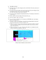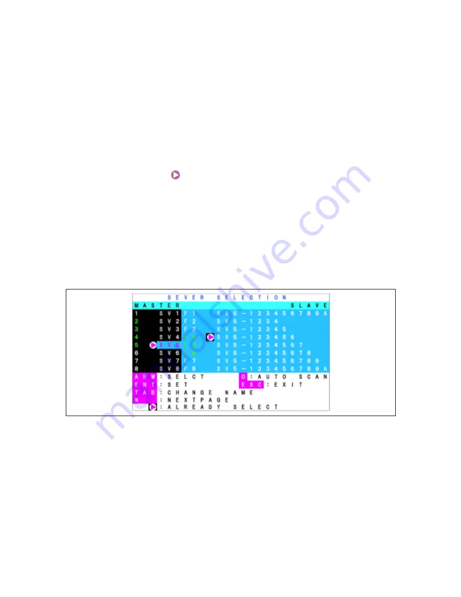
a) Description
of
screen
1.
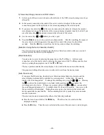
The status of the server switch unit appears on the center left side of the screen (or the area of
black background).
2.
The status of the slave unit subject to the cascade connection to the master unit appears on the
center right side of the screen (or the area of blue background).
The status is only displayed in the cascade connection.
3.
The character strings with purple background indicate the servers which may be selected now
by the cursor key.
4.
The key operation is described simply at the bottom of the screen.
5.
The server marked by
is now selected.
6.
The server with green numerals (1 to 8 for master unit, or
F1
to
F8
for slave unit) indicates
that the server is powered on.
7.
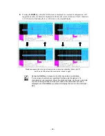
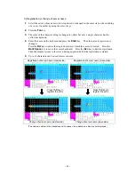
The display of OSD screen will change to either of the following depending on whether the
port selected on master side is connected in cascade or not.
n
When the selected port is not in cascade connection, 14 characters are displayed on master
side and no indication is displayed on slave side. (The OSD screen is the same as that of
non-cascade connection.)
n
When the selected port is in cascade connection, three characters are displayed on master
side and 14 characters are displayed on slave side.
OSD when the port is cascade connection is selected
-
58
-
Содержание N8191-09
Страница 6: ...シリーズ サーバスイッチユニット Server Switch Unit ユーザーズガイド User s Guide ...
Страница 21: ... xv ...

