English-5
English
Contents
For contents, please refer to the contents sheet.
Quick Start
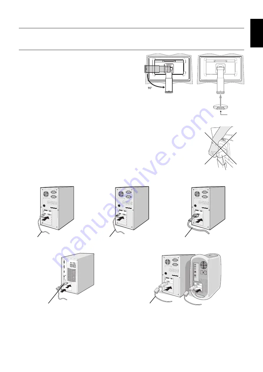
To attach the Base to the LCD stand:
1. Place monitor face down on a non-abrasive surface (
Figure 1
).
2. Please rotate the stand 90 degrees as shown in
Figure 1
.
NOTE:
Handle with care when pulling the stand.
3. Attach the base to the stand and lock screw at the base’s bottom
(
Figure 2
).
NOTE:
Reverse this procedure if you need to re-pack the monitor.
To connect the LCD monitor to your system, follow these instructions:
NOTE:
Make sure to read “Recommended Use” (page 3) before installation.
The accessories included will depend on the where the LCD monitor is to be shipped.
Do not hold Tilt cover. It can damage tilt cover (
Figure 3
).
1. Turn off the power of your computer.
2.
For a PC with DisplayPort output:
Connect the DisplayPort cable to the connector of the display
card in your system (
Figure A.1
).
For a PC with HDMI output:
Connect the HDMI cable to the connector of the display card in your
system (
Figure A.2
).
For a PC with Analog output:
Connect a 15-pin mini D-SUB signal cable to the connector of the
display card in your system (
Figure A.3
).
For a MAC with Thunderbolt output:
Connect a Mini DisplayPort to DisplayPort adapter to the
computer and then attach the DisplayPort cable to the adapter and to the display (
Figure A.4
).
For a PC or MAC with DVI digital output:
Connect the DVI signal cable to the connector of the
display card in your system (
Figure A.5
). Tighten all screws.
Figure A.1
Figure A.3
Figure A.2
DisplayPort cable
HDMI cable
15-pin mini D-SUB signal cable
DVI cable
DVI cable
Figure A.4
Figure A.5
Macintosh Cable Adapter
Macintosh Cable Adapter
NOTE:
1. When removing the DisplayPort cable, hold down the top button to release the lock.
2. Please use a High Speed HDMI cable with HDMI logo.
3. Please use a DisplayPort Certifi ed DisplayPort cable.
3. Place hands on each side of the monitor to tilt the LCD panel 30-degree angle and lift up to the highest position.
Figure 1
Figure 2
Screw
Tilt cover
Figure 3


