


APPENDIX C CONNECTORS FOR TARGET CONNECTION
User’s Manual U11595EJ5V0UM
60
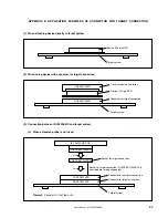
(2) When setting device
Caution
Check for abnormal conditions such as resin burrs or bent pins before setting a device on the
NQPACK100SD. Moreover, check that the hold pins of the HQPACK100SD are not broken or
bent before setting the HQPACK100SD. If there are broken or bent pins, fix them with a thin, flat
plate such as a blade.
<1>
Make sure that the NQPACK100SD is clean and the device pins are parallel (flat) before setting a device
on the NQPACK100SD. Then, after mounting the NQPACK100SD on the target board, set the device and
HQPACK100SD (refer to
Figure C-2
).
<2>
Using the screws provided with the HQPACK100SD (four locations: M2
×
6 mm), secure the
HQPACK100SD, device, and NQPACK100SD.
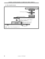
Tighten the screws in a crisscross pattern with the provided screwdriver or a screwdriver with a torque
gauge (avoid tightening only one screw strongly). Tighten the screws with 0.55 kg·f·cm (0.054 N
•
m) max.
torque. Excessive tightening may disminish conductivity.
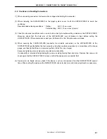
At this time, each pin is fixed inside the plastic wall dividers by the contact pin of the NQPACK100SD and
the hold pin of the HQPACK100SD (refer to
Figure C-3
). Thus, pins cannot cause shorting with pins of
neighboring devices.
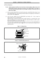
Figure C-2. Mouting Device
Fixing screws
HQPACK100SD
NQPACK100SD
Target system
Device
Figure C-3. NQPACK100SD and Device Pin
Hold pin of HQPACK100SD
Divider
Device
Pin
Contact pin of NQPACK100SD
Содержание IE-703002-MC
Страница 2: ...User s Manual U11595EJ5V0UM 2 MEMO ...


