CHAPTER 6 CAUTIONS
User’s Manual U11595EJ5V0UM
47
6.5
Pin Handling
(1) MODE0 and MODE1 pins
When the IE-703002-MC is operated on a stand-alone basis, the MODE0 and MODE1 pins are set to operate in
single mode as follows.
• MODE0: Pull down via 33 k
Ω
resistor
• MODE1: Pull up via 5.1 k
Ω
resistor
(2) RESET pin
Pull up via 5.1 k
Ω
resistor
(3) WAIT pin
Pull up via 5.1 k
Ω
resistor
(4) CKSEL pin
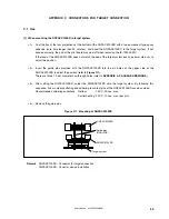
SW1 in the pod can switch the CKSEL pin between a pull-up/pull-down resistor.
(5) PLLSEL pin (V852)
SW2 in the pod can switch the PLLSEL pin between a pull-up/pull-down resistor.
Figure 6-1. Circuit Diagram of PLLSEL Pin and CKSEL Pin
V852 PLLSEL pin
3 V
SW1
GREEN
100
Ω
220
Ω
GREEN
220
Ω
33 k
Ω
3 V
SW2
100
Ω
33 k
Ω
PLLSEL
CKSEL
V852
CKSEL pin
Emulation
CPU
Содержание IE-703002-MC
Страница 2: ...User s Manual U11595EJ5V0UM 2 MEMO ...


