background image

E – 7

REM

OTE 1

PC CO

NTR

OL

REMOTE

2

AC IN


SC, TR

IGG

ER

OU

T

OU

T

IN

IN

PC C

ARD

3

5

4

1

7

8

9

2

6

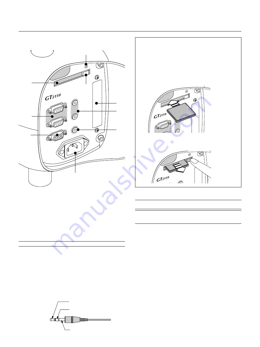
1. PC CONTROL Connectors (Mini D-Sub 9 pin)

For system expansion such as PC-Control.
IN:

connect to the external equipment such as PC.

OUT: for daisy-chaining multiple projectors and operating them with

the same external equipment. To do so, connect to a second
projector’ s IN terminal to relay the input at the IN terminal of the
first projector until all the projectors are connected.

2. REMOTE 1 Connector (Mini D-Sub 15 pin)

This terminal allows external control of the projector from either the
Switcher or from an external control. When the Switcher is used, con-
nect to the REMOTE 1 terminal on the back of the Switcher.

NOTE: This projector is compatible with the ISS-6020 Switcher.

3. REMOTE 2 Mini Jacks

IN:

wired remote control input.

OUT: for daisy-chaining multiple projectors and operating them with

the same remote control. To do so, connect to a second projec-
tor’ s IN terminal to relay the input at the IN terminal of the first
projector until all the projectors are connected.

4. SC. TRIGGER Mini Jack

Screen Trigger- When the GT2150 is powered ON the screen trigger
output sends a low voltage trigger to the screen controller and the
screen will go down.

Front Terminal Panel (Left)

When the GT2150 is powered OFF the screen trigger stops sending a
low voltage trigger to the screen controller and the screen will go up.

NOTE: Screen Controllers are supplied and supported by screen manufactures.
This option is not included with the GT2150 projector.

NOTE: Do not use this jack for anything other than intended use. Connecting
the wired remote control to the SC. TRIGGER Mini Jack causes damage to the
remote control.

5. Slot for LAN Board (Optional)

Use this connector to control the projector on a LAN. The optional LAN
kit is required when this connector is used. See the instructions in-
cluded with the optional LAN kit (GT50LAN).

6. AC IN

Connect the supplied power cable’s three-pin plug here.
Three types of power cable are supplied with this LCD projector: three-
pin type for U. S. A. and Canada. Two-pin type for Europe and Japan.

7. PC Card Slot

Insert a CompactFlash™ card here.

8. PC Card Eject Button

Press to eject a CompactFlash™ card.

9. PC Card Access Indicator

Lights while accessing a CompactFlash™ card.

Tip (12V)

Ring (0V)

Sleave (ground. 0V)

Stereo mini cable
(not supplied)

Inserting or Ejecting a CompactFlash Card

CAUTION:  DO NOT EJECT THE CompactFlash CARD, TURN
OFF THE POWER, OR UNPLUG THE POWER CABLE of the
projector while the PC card access indicator light shows that data
is being accessed. Doing so could cause damage to the
CompactFlash card.

Inserting

Insert the CompactFlash card into PC Card Slot with its TOP FAC-
ING DOWN.

IN

IN

PC CARD

PC C

ON

TRO

L

REM

OTE

2

IN

IN

PC CAR

D

Bottom

Removing

Press the PC Card Eject button. The CompactFlash card ejects
partially, then remove.

Содержание GT2150 Series

Страница 1: ...LCD Projector GT2150 User s Manual ...

Страница 2: ...echnischen Anfangseinstellungen Setup einschließlich der Einstellungen der Benutzersteuerungen Diese Kosten sind vom Händler zu tragen von dem das Produkt erworben wurde 6 Bezahlung von Transportkosten GARANZIA LIMITATA A parte la specificazione seguente la graanzia che potrebbe essere fornita dal rivenditore copre tutti i difetti di materiali o nella lavorazione in questo prodotto I seguenti non ...

Страница 3: ...E N T E R C A N C E L S E L E C T L E N S S H IF T L E F T Z O O M F O C U S U P D O W N R IG H T A U T O A D JU S T LA M P S T A T U S P O W E R O N S T A N D B Y S O U R C E LCD Projector GT2150 User s Manual ...

Страница 4: ...Federal Communications Commission does not allow any modifications or changes to the unit EXCEPT those specified by NEC Technologies in this manual Failure to comply with this gov ernment regulation could void your right to operate this equip ment This equipment has been tested and found to comply with the limits for a Class B digital device pursuant to Part 15 of the FCC Rules These limits are de...

Страница 5: ...sur le fonctionnement ou l entretien de cet appareil Ces informations doivent être lues attentivement pour éviter tout problème AVERTISSEMENT AFIN DE PREVENIR TOUT RISQUE D INCENDIE OU DE CHOC ÉLECTRIQUE N EXPOSEZ PAS CET APPAREIL À LA PLUIE OU À L HUMIDITÉ N UTILISEZ PAS LA PRISE AVEC TERRE DE L APPAREIL AVEC UNE RALLONGE OU UNE AUTRE PRISE A MOINS QUE LES TROIS BROCHES PUISSENT ÊTRE COMPLETEMENT...

Страница 6: ...o your eyes could result Keep any items such as magnifying glass out of the light path of the projector The light being projected from the lens is extensive there fore any kind of abnormal objects that can redirect light coming out of the lens can cause unpredictable outcome such as fire or injury to the eyes Do not cover the lens with the supplied lens hood cap or equivalent while the projector i...

Страница 7: ... trois minutes après l extinction du projecteur grâce à l interrupteur POWER OFF Lorsque les indicateurs POWER alimentation électrique et STATUS état clignotent alternativement ATTETION Ne pas placer le projecteur sur le côté lorsque la lampe est allumée sinon le projecteur risque d être endommagé Avant d expedier ce projecteur veuillez démonter l objectif et fixer le bouchon d objectif Le mécanis...

Страница 8: ...ler from whom you purchased the product 2 Whenever warranty service is required the original dated invoice or a copy must be presented as proof of warranty coverage In order to obtain warranty service you may be required to describe and demonstrate the problem to your dealer or to NEC Solutions 3 All products returned to NEC Solutions for service MUST have prior approval To receive approval or for...

Страница 9: ...any interference received including interference that may cause undesired operation U S Responsible Party Address Tel No NEC Technologies Inc 1250 N Arlington Heights Road Itasca Illinois 60143 630 467 5000 Type of Product Equipment Classification Models LCD Projector Class B Peripheral GT2150 We hereby declare that the equipment specified above conforms to the technical standards as specified in ...

Страница 10: ...on E 42 Color E 42 Hue E 42 Sharpness E 42 V Aperture E 42 Gamma Correction E 42 White Balance E 43 Color Temperature E 43 Brightness R G B E 43 Contrast R G B E 43 Signal Level E 43 Image E 43 Pixel Adjust E 43 Clock Phase E 43 Horizontal Vertical Position E 43 Aspect Ratio E 43 Resolution E 43 Overscan E 43 Video Filter E 44 Blanking E 44 Video Adj E 44 Noise Reduction E 44 Color Matrix E 44 Y C...

Страница 11: ...A D JU S T LA M P S T A T U S P O W E R O N S T A N D B Y S O U R C E NOTE Lenses are optional Order lenses from your NEC dealer Lens hood cap Remote control and batteries AAA x 2 String and rivet Power cable for Europe AC 220 240V Power cable for North America AC 120V Power cable for Japan AC 100V GT2150 Projector Remote cable User s manuals Japanese and English German Ferrite clamp cores for a c...

Страница 12: ...N S T A N D B Y S O U R C E Getting to Know Your GT2150 Projector Lens hood Remote sensor Terminal panel Left AC INPUT Connect the supplied power cable s three pin plug here Lens optional Lens hood cap Controls Remote sensor Ventilation outlet Built in Security Slot Foot four Rotate to fine adjust the height of each foot Terminal panel Right NOTE Slot for Kensington MicroSaver Security System This...

Страница 13: ...N D B Y S O U R C E Depression for foot 4 locations Speaker Left Remote sensor Speaker Right Remote sensor Carrying handle Lamp cover DVI L MO NO L MO NO RGB 1 RGB 2 VIDE O 1 VIDE O 2 S VI DEO AUD IO OUT R Cr G Y B Cb V H HV MON ITOR OUT R L MO NO R L MO NO R L MO NO R R REM OTE 1 PC CON TROL REMO TE 2 SC TRIG GER OUT OUT IN IN PC CARD Air filter Ventilation inlet ...

Страница 14: ... 1 S V IDE O AU DIO OU T G Y B C b V H H V L M ON O R L M ON O R L M ON O R Rivet Carrying the Projector Always carry your projector by the handle Ensure that the power cable and any other cables connecting to video sources are disconnected before moving the projector When moving the projector or when it is not in use cover the lens with the lens hood cap CAUTION Do not put the projector on its si...

Страница 15: ...election and activates items selected from the menu 7 Cancel Button Press this button to exit Menus Press this button to return the adjust ments to the last condition while you are in the adjustment or setting menu Top Features 8 Lens Shift Button Adjust the lens offset by shifting the projected image position horizon tally and or vertically 9 Zoom Button Zoom the lens in and out 10 Focus Button A...

Страница 16: ...e RGB 1 or RGB 2 input source 6 RGB 1 Input Connectors BNC Connect R G B H Horizontal sync and V Vertical sync outputs of external equipment such as the NEC ISS 6020Switcher If using a component with a combined sync SYNC output connect it to the H V terminal When using luminance and color difference signals of HDTV and DVD connect Pr Cr to the R Y to the G and Pb Cb to the B input of the projector...

Страница 17: ...sending a low voltage trigger to the screen controller and the screen will go up NOTE Screen Controllers are supplied and supported by screen manufactures This option is not included with the GT2150 projector NOTE Do not use this jack for anything other than intended use Connecting the wired remote control to the SC TRIGGER Mini Jack causes damage to the remote control 5 Slot for LAN Board Optiona...

Страница 18: ...ns work as a volume con trol 䊴 䊳 Use these buttons to change the level of a selected menu item A press of the 䊳 button executes the selection Pressing and holding CTL then pressing 䊴 button works as a Back Space key in the entry screen Pressing and holding CTL then pressing this button moves the menu slider toolbar or dialog box 6 ADJUST WHITE BAL Press to display the Color adjustment screen Press...

Страница 19: ...e Press again to restore the sound 19 MUTE OSD Press to turn off the on screen display Press again to restore the on screen display NOTE You can also turn off the on screen display forcefully by pressing and holding CTL and then pressing MUTE OSD Forced On Screen Mute Mode doing this again restores it In this case any adjustment will still change the projector s memory settings This mode is availa...

Страница 20: ... comes time to replace the batteries two AAA type will be required 1 Press and open the cover 2 Align and insert the batteries according to the and indica tions inside the case 3 Replace the cover Operating Range for Wireless Remote Control The infrared signal operates by line of sight up to a distance of ap proximately 7m 20 feet and a 60 degree angle of the remote sensor The projector will not f...

Страница 21: ...ntrol Terminal panel Left REMOTE 1 PC CONTROL REMOTE 2 AC IN SC TRIGGER OUT OUT IN IN O F F P I C T U R E A D J U S T A B C D E F G H I J K L M N O P Q R S T U U N D O C A N C E L E S T T D H E L P I N F O A U T O P I X E L V W X Y Z W H I T E B A L I M A G E O N P O W E R M E N U E N T E R 1 2 3 4 5 6 7 0 8 9 A D D R E S S P R O J E C T O R B S PC CARD Remote cable supplied ...

Страница 22: ...oject your image 3 Install the optional lens to the projector 4 Connect the supplied power cable 5 Set up the projector 6 Connect a PC VCR DVD player or other equipment 7 Make settings or adjustments on the projector Screen Size and Projection Distance Applicable lens and throw distance List of screen sizes Screen Size Diagonal Table of Throw Distances and Screen Sizes for Optional Lenses 40 60 67...

Страница 23: ...d image V height of projected image NOTE If lens is shifted in two directions combined maximum range in either direction cannot be obtained due to rounded off area near edge of lens ex ample shift up and right See diagram below Normal projection position Lens Shift Range for Desktop and Ceiling Mount Application The diagram below shows the location of the image position in the lens The lens can be...

Страница 24: ... the lens hood cap and lens hood 1 Press and hold the catches on both ends of the lens hood cap and 2 then remove it 3 Loosen the 4 screws on the lens hood using the hexagonal driver until the hexagonal driver goes into a freewheeling condition and 4 remove the lens hood The 4 screws are not removable RE MOT E1 PC CO NT RO L RE MO TE 2 SC TR IG GE R OU T OU T IN IN PC CA RD AC IN DVI DIG ITA L DVI...

Страница 25: ... T LA M P S T A T U S P O W E R O N S T A N D B Y S O U R C E 4 NOTE Leave the front lens cap for protection while mounting the lens unit 4 Reinstall the lens hood 1 Remove the front lens cap from the lens unit 2 Insert the lens hood so that the grooves on the 4 corners of the lens hood are properly lined up with the 4 catches on the projector 3 Secure the 4 screws using the hexagonal driver This ...

Страница 26: ...s indicator will start flashing After stor ing data on the CompactFlash card the POWER indicator will change to orange 3 1 5 3 Remove the CompactFlash card from the slot of the master pro jector 3 1 6 Transfer the data to the other slave projector using the CompactFlash card so that all the projectors have the same data in memory 3 1 6 1 Insert the CompactFlash card into the slot of the slave proj...

Страница 27: ...mation on the currently displayed signal select Help Source In formation Page1 6 5 Make adjustments to the slave projector NOTE See List of Menu Items Available on Link Mode on page E 62 for more information 6 5 1 Temporarily change the master projector from Master to Standalone Make sure that the slave projector is still in Slave mode 6 5 2 Display a source you want to adjust from the master proj...

Страница 28: ... more information Do not attempt to install the projector yourself Only use your projector on a solid level surface If the projector falls to the ground you can be injured and the projector severely dam aged Do not use the projector where temperatures vary greatly The pro jector must be used at temperatures between 32 F 0 C and 95 F 35 C Do not expose the projector to moisture dust or smoke This w...

Страница 29: ...ESS BS ME N U E N T E R CANCEL S E L E C T L E N S S H I F T L E F T U P D O W N R I G H T A U T O A D J U S T L A M P S T A T U S P O W E R O N S T A N D B Y S O U R C E To turn on the projector Only after you press the ON STAND BY button on the projector cabinet or POWER ON button on the remote control will the power indicator turn to green and the projector become ready to use NOTE Immediately ...

Страница 30: ... you the opportunity to select one of the seven menu languages English German French Italian Spanish Swedish and Japanese To select a menu language follow these steps 1 Use the Select or button to select one of the seven languages for the menu OFF PICTURE ADJUST ABC DEF GHI JKL MNO PQR STU UNDO CANCEL TEST PICTURE KEYSTONE AMPLITUDE ENTRYLIST SOUND OSD MUTE MAGNIFY HELP INFO POSITION AUTO PIXEL VW...

Страница 31: ...te control or the LENS SHIFT button on the projector cabinet to move the image horizontally and vertically To close the Lens Shift adjustment screen press the CANCEL button See page E 13 for Lens Shift Adjustable Range POSITION LENS CTL 2 Press and hold the CTL and press the ZOOM or button to adjust the image size You can also adjust the image size by using the ZOOM or button on the projector cabi...

Страница 32: ... the image square to the screen REMOTE1 PCCONTROL REMOTE 2 SC TRIG GER OUT OUT IN IN PC CARD ACIN DVI DIGITAL DVI DIGITAL OUTPUT L MONO L MONO RG B 2 RG B 1 VIDEO 1 VIDEO 2 S VIDEO AUDIO OUT R Cr G Y B Cb V H HV ANALOG R L MONO R L MONO R L MONO R R Up Down Each of the feet height can be changed up to 20 mm 0 78 or at angles up to 3 5 degrees ...

Страница 33: ...tor Use standard RCA audio patch cords to connect the audio from your VCR or laser disc player to your projector if your VCR or laser disc player has this capability Be careful to keep your right and left channel connections correct for stereo sound 3 Turn on the projector and the VCR or laser disc player NOTE Refer to your VCR or laser disc player owner s manual for more information about your eq...

Страница 34: ...to your projector and DVD player 2 Use the optional Component V cable to connect your DVD player to the RGB 1 input or use a D Sub 15 pin cable to the RGB 2 input of your GT2150 projector 3 Turn on the projector and the DVD player L MONO L MONO RGB 2 RGB 1 VIDEO 1 VIDEO 2 S VIDEO AUDIO OUT R Cr G Y B Cb V H HV R L MONO R L MONO R L MONO R R L MONO R OUTPUT ANALOG DVI DIGITAL DVI DIGITAL HD VCR DVD...

Страница 35: ...mputer to the projector 3 Turn on the projector and the computer 4 If the projector goes blank after a period of inactivity it may be caused by a screen saver installed on the computer L MONO L MONO RGB 2 RGB 1 VIDEO 1 VIDEO 2 S VIDEO AUDIO OUT R Cr G Y B Cb V H HV R L MONO R L MONO R L MONO R R L MONO R OUTPUT ANALOG DVI DIGITAL DVI DIGITAL RGB signal cable not supplied RGB signal cable not suppl...

Страница 36: ...he other equipment than another projector to this con nector L MONO L MONO RGB 2 RGB 1 VIDEO 1 VIDEO 2 S VIDEO AUDIO OUT R Cr G Y B Cb V H HV R L MONO R L MONO R L MONO R R L MONO R OUTPUT ANALOG DVI DIGITAL DVI DIGITAL L MONO L MONO RGB 2 RGB 1 VIDEO 1 VIDEO 2 S VIDEO AUDIO OUT R Cr G Y B Cb V H HV R L MONO R L MONO R L MONO R R L MONO R OUTPUT ANALOG DVI DIGITAL DVI DIGITAL To DVI digital Connec...

Страница 37: ... RGB input Workstation To RGBHV input Installation Instructions 1 Open and attach the ferrite clamp core to a signal cable as close as possible to the end that goes to the projector Information for Reducing Radiation of Electromagnetic Waves To reduce unnecessary radiation of electromagnetic waves use the supplied ferrite clamp core Push the catch to open the ferrite clamp core 2 Close the ferrite...

Страница 38: ...cher refer to the user s manual accompanying the ISS 6020 ISS 6020G Switcher All cables mentioned above are sold separately The RGB2 terminal will not work with the Switcher Control function To use the projector with the Switcher ISS 6020 in the Switcher Control mode When connecting with the VIDEO INPUT MODULE 6020 VID set the VIDEO MODE select switch S3001 to 8 The VIDEO MODE select switch is loc...

Страница 39: ...ches S8603 of the Switcher to RS 422 positions Set the one on the last slave Switcher to the appropriate position to match the connected equipment such as a personal computer RS 422 RS 232C for PC control of projector Set the DIP switch S8601 of the Switcher Personal Computer To REMOTE 1 To REMOTE 1 To REMOTE 2 To Slot 1 To Slot 2 To Slot 10 To RS232C To REMOTE 1 To REMOTE 2 To REMOTE 1 To REMOTE ...

Страница 40: ...1 Slave 2 Slave 3 Slave 4 Slave 5 Slave 6 Slave 7 Slave 8 Slave 9 Slave 10 ISS 6020 ISS 6020G Output to Setting of S8601 NOTE Slave numbers 1 to 10 must correspond to the master s slot numbers 1 to 10 OPEN SHORT 1 2 3 4 5 6 7 8 OPEN SHORT 1 2 3 4 5 6 7 8 OPEN SHORT 1 2 3 4 5 6 7 8 OPEN SHORT 1 2 3 4 5 6 7 8 OPEN SHORT 1 2 3 4 5 6 7 8 OPEN SHORT 1 2 3 4 5 6 7 8 OPEN SHORT 1 2 3 4 5 6 7 8 OPEN SHORT...

Страница 41: ... Switcher or a third party external control device When the Switcher is used connect it with the optional control cable 15 15 pin 50 ft 16m CTL 6010 to this connector When using with the Switcher ISS 6020 ISS 6020G connect No 1 2 6 7 9 and15 pins of the projector to the same No pins of the switcher as shown below When used with the Switcher Pin No FUNCTION 1 2 6 and 7 Sending and receiving data wh...

Страница 42: ...ol mode is set to ON the following settings are not effective Timer Power Manage ment Power Confirmation Default Source Select NOTE Pin 13 is the external remote signal terminal The projector can be controlled by the same format signal as the supplied remote control from the external controller regardless of setting on Pin 14 NOTE When turning off the power to the projector using the external cont...

Страница 43: ...tor ID 03 Remote Address 03 You can daisy chain multiple projectors and operate them separately with the same remote control in wired operation To do so 1 Use the remote control cable to connect the REMOTE 2 Output of one projector to the REMOTE 2 Input of the next projector until all the projectors are connected Only one remote control cable is supplied with each projector 2 Specify a unique proj...

Страница 44: ...IGITAL Using the PC CONTROL connectors The Link mode function allows you to adjust or set multiple projectors using the DVI DIGITAL OUTPUT and the PC CONTROL connectors Connection for Double Stacking in Link Mode Master projector Bi directional RS 232C cable not supplied Slave projector DVI cable not supplied Connect source equipment to the master projector ...

Страница 45: ...d for an extended period If you want to turn off the image briefly five minutes or less press the MUTE PICTURE button instead of turning the projector off and on The projector will display a black blue image or logo if no input signal is present Do not turn the projector off and then immediately back on The Projector needs to cool down for ONE minute before it is powered on again CAUTION Do not di...

Страница 46: ...ncel the changes use the or buttons to highlight Cancel and press the Enter button To return to the factory default select Reset then press the En ter button The default Basic Custom Menu items are Source Select RGB1 2 DVI DIGITAL Video1 2 S Video and En try List Brightness Contrast Pixel Adjust and Position NOTE Once you have selected OK on the Basic Custom Menu Edit screen you cannot cancel the ...

Страница 47: ... 1 10 in SW Level mode Displays the Select switcher Input Slot window NOTE This feature is available for SW 2 Level mode only When the SW 1 Level mode is selected pressing Source button switches to the corresponding slot without displaying the Select Slot window CTL MENU ADDRESS Displays the remote ID entry window CTL IMAGE PROJECTOR Sequentially selects the Projector Options sub menu CTL POSITION...

Страница 48: ...eo Filter Blanking Noise Reduction Color Matrix Y C Delay Telecine Motion Select Motion Level YTR Adjustment CTR Adjustment Clamp Timing Sync Protection VD Delay Gain Volume RGB Component Picture White Balance Image Video Adj Option Adj Signal Type Switcher Brightness R G B Contrast R G B R G B Y Cb Cr Y Pb Pr Clock Phase Horizontal Vertical Input Signal 1 25 1 1 33 1 1 78 1 1 85 1 2 35 1 Display ...

Страница 49: ... Message No Input Clean Filter On Off Direct Button Volume Bar Keystone Bar On Off On Off Timer Sleep Timer Timer Menu Setup Link Mode Switcher Control LAN Mode Execute Switch Active Inactive Edit Preset Time Off 0 30 1 00 1 30 2 00 Page 1 Page 2 Page 3 Page 4 Page 5 Page 6 Orientation Desktop Front Ceiling Rear Desktop Rear Ceiling Front Background Blue Black Logo S Video Mode Select Off S2 Remot...

Страница 50: ...front Radio button Use this round button to select an option in a dialog box Check box Place a checkmark in the square box to turn the option On Slide bar Indicates settings or the direction of adjustment OK button Press to confirm your setting You will return to the previous menu Cancel button Press to cancel your setting You will return to the previous menu Help button Press the Help button on t...

Страница 51: ...opy a selected signal from the list and place it on the clipboard in the projector Paste Enables you to paste the signal placed on the clipboard to any other line of the list To do this select Paste and then select the line number you want to paste to Last press ENTER Edit Enables you to change source name or assign the direct key All Delete This feature enables you to delete all the registered si...

Страница 52: ... different input terminal RGB 1 or RGB 2 respectively or assign specific remote keys for signals 1 Cut an existing signal from the Entry List 1 Select another signal other than the one currently projected because the currently projected signal cannot be cut 2 Press the ENTRY LIST button on the supplied remote control 3 After selecting the existing signal press and hold down the CTL button and then...

Страница 53: ... displayed full screen using the Advanced AccuBlend feature Overscan You can select overscan percentage for RGB signal Select the appropriate option using the SELECT 䊴 or 䊳 button NOTE When Resolution is set to Native this feature is not available and the stored settings and adjustments are invalid White Balance R G B Y Cb Cr or Y Pb Pr Gain Adjust RGB Component or HDTV Gain to match multiple proj...

Страница 54: ...detection when Adaptive is selected YTR Adjustmen not available for RGB Adjusts luminance transient time CTR Adjustment not available for RGB Adjusts chroma transient time Video Filter This feature reduces video noise Select the appropriate filter for your signal Bar 0 Off Bar 1 3 High Bar 2 3 Medium Bar full Low Blanking This feature allows you to mask any unwanted area of the screen image Blanki...

Страница 55: ...ing Tri Sync This is set when projecting HDTV video Front Porch This is set when the picture quality does not improve even though Auto or Tri Sync has been set Adjust This permits the video clamp position for each signal to be set Use Adjust when a clamp timing error occurs at the time of special analog signal reception such as 1080P Note that Adjust is not valid for doubler signals such as NTSC a...

Страница 56: ... keystone correction may not be possible when excessive keystone cor rection is used The idea is the closer you are to native resolution the better image you will see NOTE The keystone feature is not available when the test pattern or the blue back is displayed Returns all adjustments and settings to the factory preset level All Data Reset all the settings for all the signals to the fac tory prese...

Страница 57: ... manually Auto 5 sec The menu will automatically be turned off in 5 seconds if no buttons are pressed within 5 seconds Auto 10 sec The menu will automatically be turned off in 10 seconds if no buttons are pressed within 10 seconds Auto 30 sec The menu will automatically be turned off in 30 seconds if no buttons are pressed within 30 seconds Menu Page 1 5 To enable your setting select Active on the...

Страница 58: ...keystone bar on screen Off You can increase or decrease the level without having to use the keystone bar Page 3 Setup Enables you to set operating options Press OK to save your changes for all the features of Page1 Page2 Page3 Page 4 Page5 and Page 6 Page 1 Page 2 Display Select You can choose the desired status information to be displayed on the screen The desired status information will be displ...

Страница 59: ...tment manually Orientation This reorients your image for your type of projection The options are desktop front projection ceiling rear projection desktop rear projection and ceiling front projection Background Use this feature to display a blue black screen or logo when no signal is available The default background is blue S Video Mode Select This feature is used to select the S Video signal detec...

Страница 60: ... Turning on this option allows a signal to be passed through to the Monitor Output connector during standby condition This is available for an RGB signal only Last Memory The projector stores the last signal data in memory for each input RGB1 RGB2 DVI DIGITAL Video and S Video This feature will reduce switching time between sources If a commercially available switcher is connected turning on this ...

Страница 61: ...test pattern Pressing this button sequentially se lects six test patterns Displays the information for your projector such as lamp usage serial number and version number etc Page 4 Link Mode Displaying Current Status of Link Mode When selecting the tab Page 4 you will get the following dialog box Master ID Indicates the Master projector Status Indicates the status of the master projector Connected...

Страница 62: ... A N D B Y S O U R C E ME N U CANCEL S E L E C T A U T O A D J U S T S T A T U S P O W E R O N S T A N D B Y S O U R C E 2 Loosen the two screws securing the lamp housing until the screw driver goes into a freewheeling condition The two screws are not removable Remove the lamp housing by pulling out the handle NOTE There is an interlock on this case to prevent the risk of electrical shock Do not a...

Страница 63: ...O TE 2 SC TRIGG ER OUT OUT IN IN PC CARD 2 Reinstall the new filter NOTE Do not detach the sponge from the filter Do not wash the filter with soap and water Soap and water will damage the the filter membrane Be fore replacing the filter cover remove dust and dirt from the projector cabi net Keep out dust and during filter replacement 3 After you install a new filter select Projector Options Setup ...

Страница 64: ...nt et entrer en mode d attente après 1600 heures 2100 heures mode Eco de service Dans ce cas remplacez la lampe Si vous continuez à utiliser la lampe après 1500 heures 2000 heures mode Eco d utilisation l ampoule de la lampe risque d éclater et des bris de glaces risquent d être dispersés dans le boîtier de la lampe Ne les touchez pas car elles peuvent vous blesser Dans ce cas contactez votre reve...

Страница 65: ...ltre Avant de remplacer le filtre à air dépoussiérez et nettoyez le coffret du projecteur Maintenez propre pendant le remplacement du filtre 3 Après avoir installé un filtre neuve sélectionnez Options du Projecteur Réglage Page 6 Pour effacement filtre pour remettre le compteur d heures d utilisation de le filtre zéro DVI L MO NO L MO NO RGB 1 RGB 2 VIDE O 1 VIDE O 2 S VID EO AUD IO OUT R Cr G Y B...

Страница 66: ...orrect the trapezoid distortion See page E 45 Adjust the focus See page E 21 Reposition the projector to improve its angle to the screen See page E 22 Ensure that the distance between the projector and screen is within the adjustment range of the lens See page E 12 Use menus or a source button on the remote control or the cabinet to select the source you want to input Install new batteries See pag...

Страница 67: ...tion Angle GT19ZL 9 0 degree tele 11 7 degree wide GT13ZL 13 3 degree tele 16 4 degree wide GT34ZL 4 0 degree tele 6 2 degree wide Electrical Input Connections RGB YCr Cb H HV V 5 BNC 1 RCA L MONO R 1 RGB D Sub 15 pin 1 RCA L MONO R 1 DVI DIGITAL DVI D Max resolution SXGA 60Hz x 1 RCA L MONO R 1 Video BNC 1 RCA 1 RCA L MONO R 1 S Video Mini DIN 4 1 RCA L MONO R 1 PC Card Slot 1 Output Connections ...

Страница 68: ...sions 16 5 W 7 7 H 19 4 D 419 mm W 195 mm H 494 mm D not including feet Net Weight 28 3 lbs 12 8 kg not including lens Environment Operational Temperatures 32 95 F 0 to 35 C 20 80 humidity Storage Temperatures 14 122 F 10 to 50 C 20 80 humidity Regulations UL Approved UL 1950 CSA 950 Meets DOC Canada Class B requirements Meets FCC Class B requirements Meets AS NZS3548 Class B Meets EMC Directive E...

Страница 69: ... L MONO R R L MONO R OUTPUT DVI DIGITAL DVI DIGITAL ANALOG REMOTE 1 PC CONTROL REMOTE 2 AC IN SC TRIGGER OUT OUT IN IN PC CARD Lens center Lens center Optional Accessories Lens Optional lens Fixed short throw 1 0 GT10RL Optional lens Zoom 1 3 1 6 GT13ZL Optional lens Zoom 1 8 2 4 GT19ZL Optional lens Zoom 3 4 5 2 GT34ZL Lamp Replacement lamp GT50LP Ceiling Mount Kit for ceiling mount installation ...

Страница 70: ...en Y 3 Blue Cb 4 Ground 5 Ground 6 Red Ground Cr Ground 7 Green Ground Y Ground 8 Blue Ground Cb Ground 9 No Connection 10 Sync Signal Ground 11 Ground 12 Bi directional DATA SDA 13 Horizontal Sync or Composite Sync 14 Vertical Sync Signal Level Video signal 0 7Vp p Analog Sync signal TTL level 5 1 4 2 3 10 11 12 13 14 15 6 9 7 8 ...

Страница 71: ...832 1024 1152 1280 1280 1280 1152 1280 1024 1152 1280 480 576 480p 720p 1035i 1080i 1080i 350 400 400 480 480 480 480 600 600 600 600 600 768 768 768 768 864 960 1024 1024 1024 1200 1200 1200 1200 1200 480 624 768 870 1024 1024 1024 900 1024 768 900 1024 Signal Name Resolution H V Horizontal Frequency Vertical Frequency Video NTSC Video PAL SECAM Video HDTV IBM PC or Compatibles Apple Macintosh HP...

Страница 72: ...mote Control L 1 MUTE PICTURE Remote Control L 1 MUTE OSD Remote Control L 1 MUTE SOUND Remote Control L 1 VOLUME Projector Display ON L 1 Display OFF L 1 Remote Control Display ON L 1 Display OFF L 1 KEYSTONE Remote Control N AUTO Projector N Remote Control N SOURCE Projector L 1 TEST Remote Control N PC Control All Each letter used in the above note means the following Letter Master projector Sl...

Страница 73: ...en correctly This will become more apparent when displaying small text and detailed graphics 1 Note Gravity Stacking Two GT2150 Projectors The optional lenses for GT2150 have different geometrical distortions in wide zoom and tele Select the best zoom position for stacking where the geometrical distortion is as small as possible The recommended throw distances are as follows Lens position Horizont...

Страница 74: ...Printed in Japan 7N8P0631 ...

Отзывы: