


1-6 System Overview
System Board Features
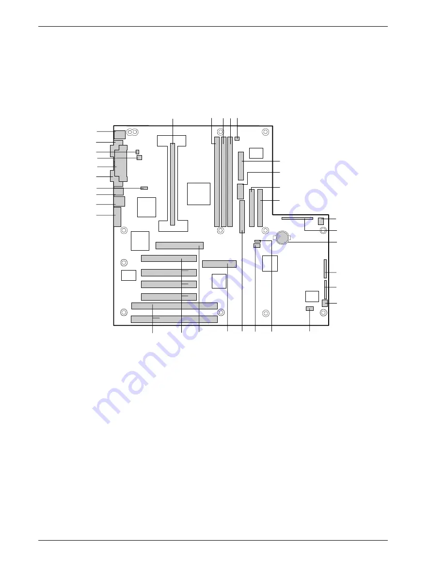
The system board offers a “flat” design with the processor and memory
subsystems residing on the board. This figure shows the major
components on the system board. The following subsections describe
the system board major components.
A
B C D E
F
G
H
I
J
K
L
M
N
O
P
Q
R
S
U
V
W
X
Y
Z
AA
BB
CC
DD
EE
FF
GG
T
A.
Processor connector
R.
Reserved
B.
DIMM slot 3
S.
Diskette drive connector
C.
DIMM slot 2
T.
Wide SCSI connector
D.
DIMM slot 1
U.
Reserved
E.
Reserved
V.
PCI slots for add in boards
F.
ATX power connector
W.
ISA slots for add in boards
G.
Reserved
X.
VGA monitor port
H.
Secondary IDE connector
Y.
USB connectors
I.
Primary IDE connector
Z.
RJ-45 network connector
J.
System fan connector
AA.
WOL enable jumper (not used)
K.
AT front panel connector
BB.
Serial port 2 connector
L.
Lithium backup battery
CC.
Parallel port connector
M.
Configuration jumper block
DD.
Fan connector (not used)
N.
Configuration jumper block
EE.
Chassis intrusion connector
O.
System fan connector (not used)
FF.
Serial port 1 connector
P.
Reserved
GG.
Keyboard and Mouse connectors
Q.
Reserved
System Board
Содержание ES1400
Страница 1: ... U s e r s G u i d e SERVER ES1400 ...
Страница 2: ...xxx ...
Страница 3: ... U s e r s G u i d e SERVER ES1400 ...
Страница 38: ...2 12 Setting Up the System ...
Страница 102: ......
Страница 124: ...5 22 Problem Solving ...
Страница 125: ...A System Cabling Before You Begin Static Precautions Standard Configuration RAID Configuration ...
Страница 131: ...System Cabling A 7 WIDE SCSI CABLE 68 pins IDE CABLE 40 pins Standard System Cable Routing ...
Страница 134: ...A 10 System Cabling WIDE SCSI CABLE 68 pins IDE CABLE 40 pins RAID System Cable Routing ...
Страница 135: ...B System Setup Utility System Setup Utility SSU Creating SSU Diskettes Running the SSU Exiting the SSU ...
Страница 168: ......
Страница 180: ......
Страница 185: ...Index 3 ...
Страница 186: ......
Страница 187: ...xx ...
Страница 188: ... ...