Electra Elite
Issue 6
System Hardware Manual
3 - 7
7.2.2
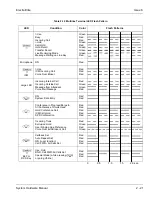
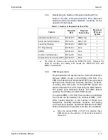
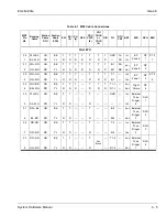
Determining the Number of Required Interface ETUs
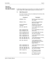
Table 3-1 Number of Required Interface ETUs
lists each
feature and the associated hardware necessary for the
operation of the feature.
Table 3-1 Number of Required Interface ETUs
7.2.3
PBR Requirements
The Electra Elite 192 system has four built-in Push Button
Receiver (PBR) circuits on the CPUB( )-U10 ETU. The
PBR circuit detects and translates DTMF tones generated
by Single Line Telephones, facsimile machines, modems,
or analog voice mail ports. Incoming DTMF signals can
also be detected from a CO trunk using the DISA feature.
The system Auto Attendant feature and DISA feature
must use the CPUB( )-U10 ETU PBR circuits.
An optional PBR( )-U10 ETU that provides an additional
four circuits can be installed. The number of PBR( )-U10
ETUs needed depends on the number of Single Line
Telephones, facsimile machines, modems, and analog
voice mail ports needed. Automated Attendant and DISA
trunks connected to the system must also be considered.
When the optional PBR( )-U10 ETU is installed, these
PBR circuits can be used only. for SLI ports connected to
the system.
Feature
Required
ETU
Required
Feature Key
Maximum
ETUs per
System
ANI/Caller ID (Refer to
)
MIFM-U10
KMM(1.0)U
1
Automatic Call Distribution
MIFA-U10
KMA(1.0)U
1
Least Cost Routing
MIFM-U10
KMM(1.0)U
1
PC Programming
MIFM-U10
None
1
SMDR
MIFM-U10
None
1
Uniform Call Distribution
MIFA-U10
None
1
Wireless Service Console (WSC) MIFM-U10
None
1
The Caller ID feature works without the MIFM-U10 ETU. However, the
Caller ID scrolling and dialing both require the MIFM-U10 ETU with
KMM(1.0)U attached.
Содержание Electra Elite 192
Страница 2: ...SYSTEM HARDWARE MANUAL Stock Number 750363 Issue 6 Series 6000 192 ...
Страница 3: ......
Страница 5: ......
Страница 9: ...THIS PAGE INTENTIONALLY LEFT BLANK ...
Страница 10: ...Regulatory Information ...
Страница 11: ......
Страница 20: ......
Страница 52: ...Issue 6 Electra Elite xxxii List of Tables THIS PAGE INTENTIONALLY LEFT BLANK ...
Страница 73: ...Electra Elite Issue 6 System Hardware Manual 1 21 THIS PAGE INTENTIONALLY LEFT BLANK ...
Страница 74: ...Issue 6 Electra Elite 1 22 Introduction ...
Страница 92: ...Issue 6 Electra Elite 2 18 System Specifications Output Impedance 600 Ω Relay Contact Rating 500 mA 24 Vdc ...
Страница 96: ...Issue 6 Electra Elite 2 22 System Specifications ...
Страница 104: ...Issue 6 Electra Elite 3 8 Hardware Requirements THIS PAGE INTENTIONALLY LEFT BLANK ...
Страница 213: ...Electra Elite Issue 6 System Hardware Manual 5 67 Figure 5 39 FMS 8 U10 ETU ...
Страница 252: ...Issue 6 Electra Elite 5 106 Installing Electronic Telephone Units THIS PAGE INTENTIONALLY LEFT BLANK ...
Страница 282: ...Issue 6 Electra Elite 6 30 Installing Electra Elite Multiline Terminals THIS PAGE INTENTIONALLY LEFT BLANK ...
Страница 336: ...Issue 6 Electra Elite 7 54 Installing Optional Equipment THIS PAGE INTENTIONALLY LEFT BLANK ...
Страница 342: ...Issue 6 Electra Elite 8 6 Installing Electra Professional Equipment THIS PAGE INTENTIONALLY LEFT BLANK ...
Страница 368: ...Issue 6 Electra Elite A 4 Glossary of Abbreviations THIS PAGE INTENTIONALLY LEFT BLANK ...
Страница 369: ...SYSTEM HARDWARE MANUAL NEC America Inc Issue 6 Series 6000 192 ...

