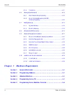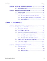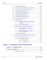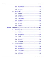
Issue 6
Electra Elite
xiv
Table of Contents
Section 3
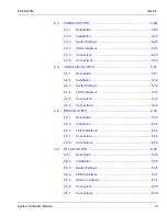
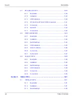
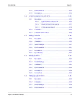
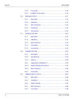
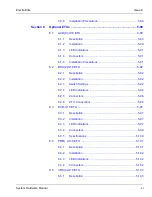
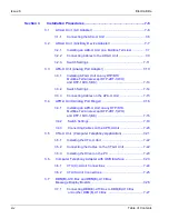
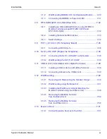
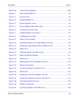
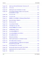
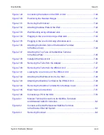
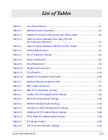
Installation Procedures ................................................................. 7-6
3.1
ACA-U Unit (AC Adapter) .......................................................... 7-6
3.1.1
Connecting the ACA-U Unit ...............................................7-6
3.2
ADA-U Unit (Ancillary Device Adapter) ...................................... 7-7
3.2.1
Installing an ADA-U Unit on a Multiline Terminal ...............7-7
3.2.2
Connecting Cables to the ADA-U Unit ...............................7-9
3.2.3
Switch Settings ................................................................7-11
3.3
APA-U Unit (Analog Port Adapter) ............................................ 7-13
3.3.1
Installing APA-U Unit on any DTP/DTU
Multiline Terminal except DTP-2DT-1(WH)
and DTP-16HC-1(BK). .....................................................7-13
3.3.2
Switch Settings ................................................................7-14
3.3.3
Connecting Cables on the APA-U Unit ............................7-15
3.4
APR-U Unit (Analog Port Ringer) .............................................. 7-16
3.4.1
Installing an APR-U Unit on any DTP/DTU
Multiline Terminal except DTP-2DT-1(WH)
and DTP-16HC-1(BK) ......................................................7-16
3.4.2
Switch Settings ................................................................7-19
3.4.3
Connecting Cables on the APR-U Unit ...........................7-20
3.5
CTA-U Unit (Computer Telephony Application) ....................... 7-21
3.5.1
Installing the CTA-U Unit .................................................7-22
3.5.2
Connecting the Cables on the CTA-U Unit ......................7-22
3.5.3
Installing the Driver on the PC .........................................7-23
3.6
Computer Telephony Adapter with USB Interface .................... 7-23
3.6.1
CTU(C)-U Unit Connections ............................................7-24
3.6.2
CTU(S) Unit Connections ................................................7-25
3.7
DBM(B)-U10 Box and DBM(E)-U10 Box
Message Display Boards .......................................................... 7-26
3.7.1
Connecting DBM(E)-U10 Box to DBM(B)-U10 Box
or Another DBM(E)-U10 Box ..........................................7-27
Содержание Electra Elite 192
Страница 2: ...SYSTEM HARDWARE MANUAL Stock Number 750363 Issue 6 Series 6000 192 ...
Страница 3: ......
Страница 5: ......
Страница 9: ...THIS PAGE INTENTIONALLY LEFT BLANK ...
Страница 10: ...Regulatory Information ...
Страница 11: ......
Страница 20: ......
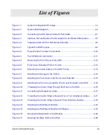
Страница 52: ...Issue 6 Electra Elite xxxii List of Tables THIS PAGE INTENTIONALLY LEFT BLANK ...
Страница 73: ...Electra Elite Issue 6 System Hardware Manual 1 21 THIS PAGE INTENTIONALLY LEFT BLANK ...
Страница 74: ...Issue 6 Electra Elite 1 22 Introduction ...
Страница 92: ...Issue 6 Electra Elite 2 18 System Specifications Output Impedance 600 Ω Relay Contact Rating 500 mA 24 Vdc ...
Страница 96: ...Issue 6 Electra Elite 2 22 System Specifications ...
Страница 104: ...Issue 6 Electra Elite 3 8 Hardware Requirements THIS PAGE INTENTIONALLY LEFT BLANK ...
Страница 213: ...Electra Elite Issue 6 System Hardware Manual 5 67 Figure 5 39 FMS 8 U10 ETU ...
Страница 252: ...Issue 6 Electra Elite 5 106 Installing Electronic Telephone Units THIS PAGE INTENTIONALLY LEFT BLANK ...
Страница 282: ...Issue 6 Electra Elite 6 30 Installing Electra Elite Multiline Terminals THIS PAGE INTENTIONALLY LEFT BLANK ...
Страница 336: ...Issue 6 Electra Elite 7 54 Installing Optional Equipment THIS PAGE INTENTIONALLY LEFT BLANK ...
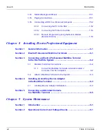
Страница 342: ...Issue 6 Electra Elite 8 6 Installing Electra Professional Equipment THIS PAGE INTENTIONALLY LEFT BLANK ...
Страница 368: ...Issue 6 Electra Elite A 4 Glossary of Abbreviations THIS PAGE INTENTIONALLY LEFT BLANK ...
Страница 369: ...SYSTEM HARDWARE MANUAL NEC America Inc Issue 6 Series 6000 192 ...


