NEC 42XP10 - PlasmaSync - 42

English

English-6

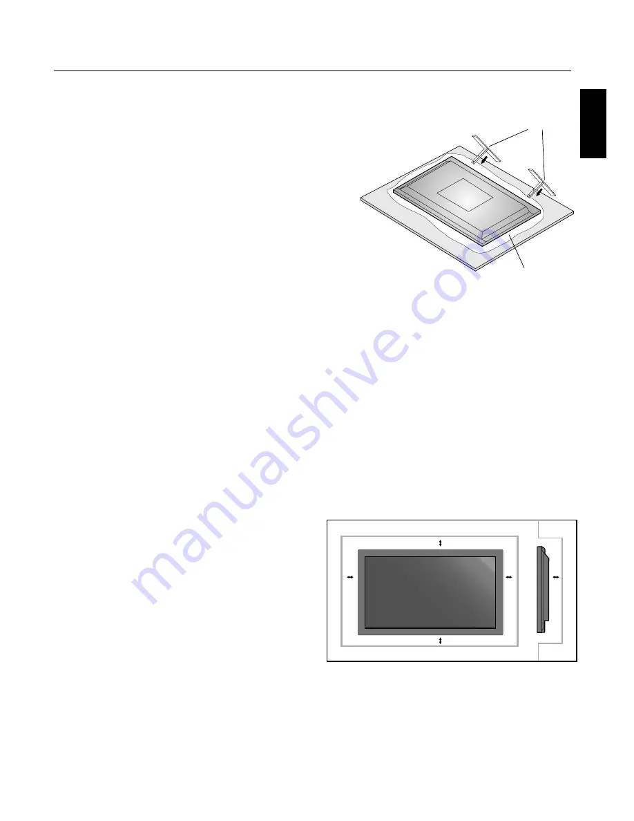
Using Optional Stand/Mounts

An optional stand or mounting apparatus can be installed .

When stand or mounting apparatus is to be installed 
while the unit is face-down (Figure 1), be sure to lay the 
protective sheet (the foam sheet that the unit was wrapped 
in) underneath the unit  on order to prevent damage to the 
screen. 

Th

  is unit must be used with a stand or some type of 

mounting apparatus. Th

  is unit is not designed for use 

without additional support.

For correct Installation and Mounting it is 
recommended to use a trained, authorized dealer.

Failure to follow correct mounting procedures could 
result in dame to the unit or to the installer.

Product warranty does not cover damage caused by 
improper installation.

CAUTION:

To install, follow those instructions included with the 
stand or mounting apparatus. Use only those devices 
recommended by the manufacturer.

Make sure to install stand or mounting apparatus to the 
unit while on a surface that is strong and stable enough 
to support the weight of the unit, such as a fl oor or 
sturdy table.

Use the specifi ed clasps for installation.

Take necessary steps to prevent the unit from tipping or 
falling.

Mounting Location

Th

  e ceiling and wall must be strong enough to support the 

monitor and mounting accessories.

DO NOT install in locations where a door or gate can hit 
the unit.

DO NOT install in areas where the unit will be subjected 
to strong vibrations and dust.

DO NOT install near where the main power supply 
enters the building.

DO NOT install in where people can easily grab and 
hang onto the unit or the mounting apparatus.

When mounting in an enclosure or in a recessed area, as 
in a wall, leave at least 2 inches (50mm) of space between 
the monitor and the wall for proper ventilation (Figure 2).

Allow adequate ventilation or provide air conditioning 
around the monitor, so that heat can properly dissipate 
away from the unit and mounting apparatus.

50mm (2")

50mm (2")

50mm (2")

50mm (2")

50mm (2")

Installation

Figure 2

Figure 1

Table

Optional table top stand

Protective Sheet

Содержание 42XP10 - PlasmaSync - 42" Plasma Panel

Страница 1: ...PlasmaSync 42XP10 PlasmaSync 50XP10 PlasmaSync 60XP10 EXIT MUTE INPUT English User s Manual...

Страница 2: ...Package Contents Plasma Monitor Remote control and AA Batteries Power cord Users Manual CD ROM Start Up Guide Paper CD ROM Main Power Switch cover and screw Cable clamps...

Страница 3: ...r Display Digital Zoom Pointer Main Power Switch Cover English 12 Remote Control ID English 13 On Screen Display OSD Using the OSD English 14 OSD English 15 Operation Picture Size Using Video Signals...

Страница 4: ...ndustries Alliance www eiae org 16 Damage Requiring Service The appliance should be serviced by qualified service personnel when A The power supply cord or the plug has been damaged or B Objects have...

Страница 5: ...s equipment generates uses and can radiate radio frequency energy and if not installed and used in accordance with the instructions may cause harmful interference to radio communications However there...

Страница 6: ...n cord or with outlets unless the prongs can be inserted fully The power supply cord you use must have been approved by and comply with the safety standards of your country Type H05VV F 3G 1mm2 should...

Страница 7: ...Human Factors Engineering of Visual Display Terminal Workstations ANSI HFS Standard No 100 1988 Published by The Human Factors and Ergonomics Society P O Box 1369 Santa Monica California 90406 Cleanin...

Страница 8: ...se complementary or pastel colors whenever possible Avoid displaying images with few colors and distinct sharply defined borders between colors Plasma monitor driving sound The panel of the Plasma mon...

Страница 9: ...g apparatus to the unit while on a surface that is strong and stable enough to support the weight of the unit such as a floor or sturdy table Use the specified clasps for installation Take necessary s...

Страница 10: ...itor should be rotated clockwise so that the left side is moved to the top and the LED indicator light is on the bottom This will allow for proper ventilation and will extend the lifetime of the monit...

Страница 11: ...chargeable alkaline or manganese batteries There is a risk of explosion if batteries are replaced incorrectly Operating Range for the Remote Control Point the top of the remote control toward the moni...

Страница 12: ...OSD menu is off Exits from the current menu being displayed to the previous menu within the OSD 9 Remote control sensor and Power indicator Receives the signal when using the wireless remote control G...

Страница 13: ...ment such as a DVD player HDTV device or set top box This input can be used with an RGB or component source For proper operation select BNC INPUT in the OPTION1 OSD menu 7 AUDIO2 Input the audio signa...

Страница 14: ...re mode S BY S Side by side mode SINGLE Returns to normal mode SWAP Swaps the Split Screen images When the QUICK SWAP function see OSD OPTION4 is ON SWAP can be used to change signal input Single scre...

Страница 15: ...e position or enlarge the image on the screen 1 Be sure ZOOM NAV function is off Press the ZOOM button or to display the magnifying glass Press the ZOOM button to enlarge the image Press the ZOOM butt...

Страница 16: ...ode press the REMOTE ID RESET button and hold down for 2 seconds In order for this feature to work properly the display must be assigned a Monitor ID number The Monitor ID number can be assigned under...

Страница 17: ...nctions may be available To access all functions the Advanced OSD option must be turned on in the ADVANCED OSD menu PICTURE AUDIO SCREEN OPTION1 ADVANCED OSD OFF NEXT PAGE SEL ENTER MAIN MENU 1 2 EXIT...

Страница 18: ...bled GAIN RED The WHITE BALANCE appears when the SET button is pressed on the COLOR TEMP OSD menu GAIN RED GREEN BLUE Adjusts the white level of the white balance 50 YES GAIN GREEN 50 YES GAIN BLUE 50...

Страница 19: ...n about inputs screen size etc is shown OFF No information is shown ON YES OSD POSITION Change the position of the menu between 1 and 6 Press or to adjust 1 YES OSD ORBITER ON The menu position interm...

Страница 20: ...ACK LEVEL LOW NO PROTOCOL SET Sets protocol setting for use with RS 232C connection OFF When NEC protocol is used normal ON When special protocol is used Consult dealer for details of protocol OFF YES...

Страница 21: ...arance of the sub screen NORMAL YES SUB P RATE Sets the transparency of the sub screen 100 YES ZOOM NAV Sets the position of the zoom navigation image BTM LFT YES PIC FREEZE Sets the position of the c...

Страница 22: ...o 2 35 1 Image is expanded at a 2 35 1 ratio to fill the entire screen The screen is filled vertically however some information will be lost on the left and right sides of the image Available for the...

Страница 23: ...panded to fill the entire screen ZOOM Vertically and horizontally expands the picture while maintaining the correct aspect ratio TRUE The image is displayed at the native resolution When using a VGA o...

Страница 24: ...D HD2 SCART1 SCART2 SCART3 VGA RGBHV DVI VIDEO1 YES YES YES YES YES YES YES VIDEO2 YES YES YES YES YES YES YES S VIDEO YES YES YES YES YES YES YES DVD HD1 YES YES YES YES YES YES YES DVD HD2 YES YES Y...

Страница 25: ...EO DVD HD or RGB button The input selection may also be changed by pressing the INPUT button on the front of the unit Adjusting the OSD controls 1 To make the desired picture active press the SELECT F...

Страница 26: ...4 NO 3 NO 1 NO 2 NO 32 NO 33 NO 34 NO 35 NO 36 NO 37 NO 38 NO 39 NO 40 NO 41 NO 42 NO 43 NO 44 NO 45 NO 46 NO 47 NO 48 NO 49 NO 50 NO 51 NO 52 NO 53 NO 54 NO 55 NO 56 NO 7 NO 8 NO 9 NO 10 NO 11 NO 12...

Страница 27: ...ng the Program Timer s Input option is not available The input used will use the input that is programmed for the Repeat Timer program Up to 10 individual PROGRAM TIMER schedules can be set When sched...

Страница 28: ...State4 State1 State2 State3 When a STATE setting is set to OFF i e STATE1 ON STATE2 ON STATE3 OFF STATE4 ON the repeat timer schedules use all but STATE3 State1 State2 State4 State1 State2 Repeat Tim...

Страница 29: ...ID number can be set within a range from 1 to 26 or set to ALL No two monitors should share the same Monitor ID number It is recommended to number each monitor in a daisy chain sequentially from 1 The...

Страница 30: ...IT NONE STOP BIT 1 bit FLOW CONTROL NONE 2 Control command diagram The command is structured by the address code function code data code and end code The length of the command is different for each fu...

Страница 31: ...rent activity changing of the input signal etc Example Turn the power ON is for ASCII code Sending commands from the PC etc Status code from Plasma monitor Meaning 30 30 21 0D 0 0 Command for POWER ON...

Страница 32: ...4Dh 70h 31h Picture Mode STANDARD vM p2 76h 4Dh 70h 32h Picture Mode CINEMA1 vM p3 76h 4Dh 70h 33h Picture Mode CINEMA2 vM p4 76h 4Dh 70h 34h Picture Mode DEFAULT vM p5 76h 4Dh 70h 35h 5 Read command...

Страница 33: ...er or other input device Use the OSD screen controls to focus and adjust display by increasing or decreasing the clock phase total When the display mode is changed the OSD Image Adjust settings may ne...

Страница 34: ...G M N SECAM 4 43NTSC PAL60 Output Signal VIDEO1 and VGA can also be used as OUTPUT terminals VGA 15pin Mini D sub Analog RGB Analog RGB Video 0 7V p p with 75 ohm terminated Separate HV sync TTL level...

Страница 35: ...B G M N SECAM 4 43NTSC PAL60 Output Signal VIDEO1 and VGA can also be used as OUTPUT terminals VGA 15pin Mini D sub Analog RGB Analog RGB Video 0 7V p p with 75 ohm terminated Separate HV sync TTL le...

Страница 36: ...M N SECAM 4 43NTSC PAL60 Output Signal VIDEO1 and VGA can also be used as OUTPUT terminals VGA 15pin Mini D sub Analog RGB Analog RGB Video 0 7V p p with 75 ohm terminated Separate HV sync TTL level...

Страница 37: ...Neg Pos 3 1280X768 2 s e Y s e Y 6 5 8 9 6 3 3 Yes Yes Neg Pos 5 1280X768 s e Y s e Y 8 7 5 2 7 4 3 Yes Yes Neg Pos 6 1280X768 35 1280 X 800 Wide XGA s e Y s e Y 7 9 4 8 9 5 Yes Yes Neg Pos 4 1280X80...

Страница 38: ...RGBHV Yes Yes Yes Yes Yes Yes Yes 3 133 480P 59 9 31 5 SCART1 3 Yes Yes Yes Yes Yes Yes Yes 3 2 480P 134 576P 3 s e Y s e Y s e Y s e Y s e Y s e Y s e Y 3 1 3 0 5 HD 135 720P 3 s e Y s e Y s e Y s e...

Страница 39: ...9 5 2 3 Yes Yes Yes Yes Neg Pos 3 1280X768 2 33 s e Y s e Y 6 5 8 9 6 Yes Yes Neg Pos 5 1280X768 34 72 57 8 Yes Yes Yes Yes Neg Pos 6 1280X768 35 1280 X 800 Wide XGA s e Y s e Y 7 9 4 8 9 5 Yes Yes N...

Страница 40: ...I 4 50 15 6 RGBHV Yes Yes Yes Yes Yes Yes Yes 3 133 480P 59 9 31 5 SCART1 3 Yes Yes Yes Yes Yes Yes Yes 3 2 480P 134 576P 50 31 3 Yes Yes Yes Yes Yes Yes Yes 3 HD 135 720P 3 s e Y s e Y s e Y s e Y 5...

Страница 41: ...Neg 3 1280X768 1 s e Y s e Y 8 7 4 9 9 5 2 3 Yes Yes Neg Pos 3 1280X768 2 s e Y s e Y 6 5 8 9 6 3 3 Yes Yes Neg Pos 5 1280X768 s e Y s e Y 8 7 5 2 7 4 3 Yes Yes Neg Pos 6 1280X768 35 1280 X 800 Wide X...

Страница 42: ...RGBHV Yes Yes Yes Yes Yes Yes Yes 3 133 480P 59 9 31 5 SCART1 3 Yes Yes Yes Yes Yes Yes Yes 3 2 480P 134 576P 3 s e Y s e Y s e Y s e Y s e Y s e Y s e Y 3 1 3 0 5 HD 135 720P 3 s e Y s e Y s e Y s e...

Страница 43: ...B Input DVI D DVI 1 TX2 9 TX1 17 TX0 2 TX2 10 TX1 18 TX0 3 Shield TX2 TX4 11 Shield TX1 TX3 19 Shield TXP TX5 4 NC 12 NC 20 NC 5 NC 13 NC 21 NC 6 DDC Serial Clock 14 5 power 22 Shield TXC 7 DDC Serial...

Страница 44: ...in compliance with Council Directive 73 23 EEC EN 60950 1 Council Directive 89 336 EEC EN 55022 EN 61000 3 2 EN 61000 3 3 EN 55024 and marked with NEC Display Solutions Ltd 4 13 23 Shibaura Minato Ku...

Отзывы: