NEC 42XP10 - PlasmaSync - 42

English-7

Mounting on Ceiling

Ensure that the ceiling is sturdy enough to support the 
weight of the unit and the mounting apparatus over 
time, against earthquakes, unexpected vibrations, and 
other external forces.

Be sure the unit is mounted to a solid structure within 
the ceiling, such as a support beam. Secure the monitor 
using bolts, spring lock washers, washer and nut.

DO NOT mount to areas that have no supporting 
internal structure. DO NOT use wood screws or anchor 
screws for mounting. DO NOT mount the unit to trim 
or to hanging fi xtures.

Maintenance

Periodically check for loose screws, gaps, distortions, 
or other problems that may occur with the mounting 
apparatus. If a problem is detected, please refer to 
qualifi ed personnel for service.

Regularly check the mounting location for signs of 
damage or weakness that may occur over time.

Please note the following when 
mounting on wall or ceiling.

When using mounting accessories other than those that 
are NEC approved, they must comply with the VESA-
compatible (FDMlv1) mounting method.

NEC strongly recommends 
using size M8 screws 
(16mm + thickness of 
bracket in length). If using 
screws longer than 16mm, 
check the depth of the 
hole.(Recommended Fasten 
Force: 1125 - 1375N•cm)
NEC recommends 
mounting interfaces that 
comply with UL1678 
standard in North America.
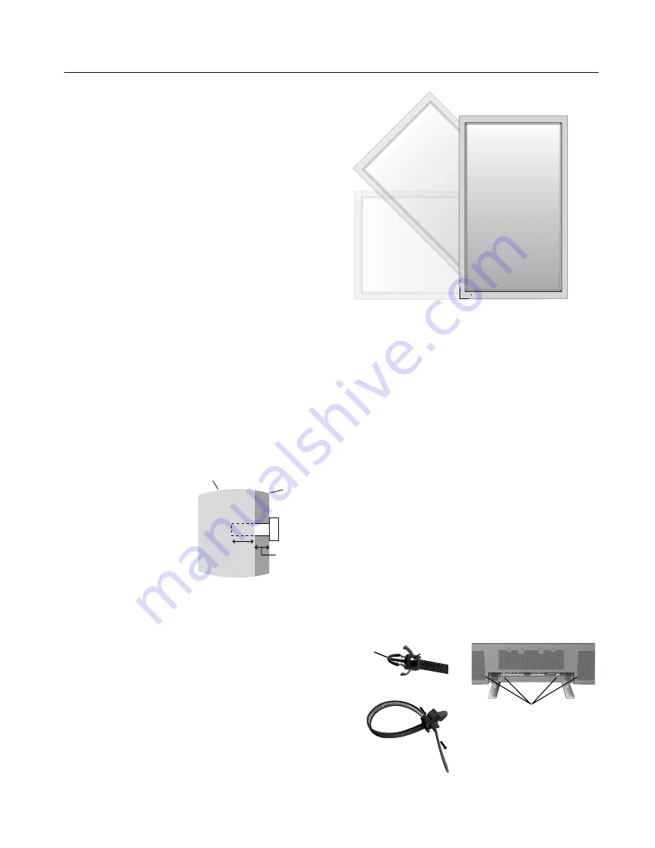
Orientation

When using the display in the portrait position, the monitor 
should be rotated clockwise so that the left  side is moved to 
the top and the LED indicator light is on the bottom. Th

 is 

will allow for proper ventilation and will extend the lifetime 
of the monitor. Improper ventilation may shorten the 
lifetime of the monitor.

 When using the display in the portrait position, please turn 
the Cooling Fan "ON" in the OPTION2 OSD menu.

EXIT

MUTE

INPUT

EXIT

MUTE

INPUT

Cable Management

To conveniently manage cables, use the cable clamps 
provided to bundle the power cord together with the signal 
and audio cables at the back of the display.

To attach cable clamps:

1. Attach the cable clamps to the display. Insert the anchor of 
the clamp into the hole on the back of the display. Th

 ere are 4 

cable clamps and 4 clamp holes on the unit.

2. Aft er the cable clamp is positioned on the display, wrap the 
end around the cables. Place the end of the clamp into the 
slot near the anchor. Pull until cables are snug.

Clamps are designed to stay in place. Once in position, they 
will be diffi

  cult to remove.

3. Cables can be routed to the right or left  of the clamp. Use 
the beaded bands to secure the cables together along their 
length. Make sure the cables are fully supported.

To detach clamps:

Using pliers, twist the clamp 90 degrees and pull outward. 
It is possible that the clamp can weaken over time and 
removing it may cause damage to the clamp.

Installation


- continued

Holes for Clamp 

anchors

16mm

Anchor

Slot

Closed Clamp

Screw length should equal 
depth of hole (16mm) + the 
thickness of mounting bracket.

Unit

Mounting 
Bracket

Screw

Thickness 
of  Bracket

Содержание 42XP10 - PlasmaSync - 42" Plasma Panel

Страница 1: ...PlasmaSync 42XP10 PlasmaSync 50XP10 PlasmaSync 60XP10 EXIT MUTE INPUT English User s Manual...

Страница 2: ...Package Contents Plasma Monitor Remote control and AA Batteries Power cord Users Manual CD ROM Start Up Guide Paper CD ROM Main Power Switch cover and screw Cable clamps...

Страница 3: ...r Display Digital Zoom Pointer Main Power Switch Cover English 12 Remote Control ID English 13 On Screen Display OSD Using the OSD English 14 OSD English 15 Operation Picture Size Using Video Signals...

Страница 4: ...ndustries Alliance www eiae org 16 Damage Requiring Service The appliance should be serviced by qualified service personnel when A The power supply cord or the plug has been damaged or B Objects have...

Страница 5: ...s equipment generates uses and can radiate radio frequency energy and if not installed and used in accordance with the instructions may cause harmful interference to radio communications However there...

Страница 6: ...n cord or with outlets unless the prongs can be inserted fully The power supply cord you use must have been approved by and comply with the safety standards of your country Type H05VV F 3G 1mm2 should...

Страница 7: ...Human Factors Engineering of Visual Display Terminal Workstations ANSI HFS Standard No 100 1988 Published by The Human Factors and Ergonomics Society P O Box 1369 Santa Monica California 90406 Cleanin...

Страница 8: ...se complementary or pastel colors whenever possible Avoid displaying images with few colors and distinct sharply defined borders between colors Plasma monitor driving sound The panel of the Plasma mon...

Страница 9: ...g apparatus to the unit while on a surface that is strong and stable enough to support the weight of the unit such as a floor or sturdy table Use the specified clasps for installation Take necessary s...

Страница 10: ...itor should be rotated clockwise so that the left side is moved to the top and the LED indicator light is on the bottom This will allow for proper ventilation and will extend the lifetime of the monit...

Страница 11: ...chargeable alkaline or manganese batteries There is a risk of explosion if batteries are replaced incorrectly Operating Range for the Remote Control Point the top of the remote control toward the moni...

Страница 12: ...OSD menu is off Exits from the current menu being displayed to the previous menu within the OSD 9 Remote control sensor and Power indicator Receives the signal when using the wireless remote control G...

Страница 13: ...ment such as a DVD player HDTV device or set top box This input can be used with an RGB or component source For proper operation select BNC INPUT in the OPTION1 OSD menu 7 AUDIO2 Input the audio signa...

Страница 14: ...re mode S BY S Side by side mode SINGLE Returns to normal mode SWAP Swaps the Split Screen images When the QUICK SWAP function see OSD OPTION4 is ON SWAP can be used to change signal input Single scre...

Страница 15: ...e position or enlarge the image on the screen 1 Be sure ZOOM NAV function is off Press the ZOOM button or to display the magnifying glass Press the ZOOM button to enlarge the image Press the ZOOM butt...

Страница 16: ...ode press the REMOTE ID RESET button and hold down for 2 seconds In order for this feature to work properly the display must be assigned a Monitor ID number The Monitor ID number can be assigned under...

Страница 17: ...nctions may be available To access all functions the Advanced OSD option must be turned on in the ADVANCED OSD menu PICTURE AUDIO SCREEN OPTION1 ADVANCED OSD OFF NEXT PAGE SEL ENTER MAIN MENU 1 2 EXIT...

Страница 18: ...bled GAIN RED The WHITE BALANCE appears when the SET button is pressed on the COLOR TEMP OSD menu GAIN RED GREEN BLUE Adjusts the white level of the white balance 50 YES GAIN GREEN 50 YES GAIN BLUE 50...

Страница 19: ...n about inputs screen size etc is shown OFF No information is shown ON YES OSD POSITION Change the position of the menu between 1 and 6 Press or to adjust 1 YES OSD ORBITER ON The menu position interm...

Страница 20: ...ACK LEVEL LOW NO PROTOCOL SET Sets protocol setting for use with RS 232C connection OFF When NEC protocol is used normal ON When special protocol is used Consult dealer for details of protocol OFF YES...

Страница 21: ...arance of the sub screen NORMAL YES SUB P RATE Sets the transparency of the sub screen 100 YES ZOOM NAV Sets the position of the zoom navigation image BTM LFT YES PIC FREEZE Sets the position of the c...

Страница 22: ...o 2 35 1 Image is expanded at a 2 35 1 ratio to fill the entire screen The screen is filled vertically however some information will be lost on the left and right sides of the image Available for the...

Страница 23: ...panded to fill the entire screen ZOOM Vertically and horizontally expands the picture while maintaining the correct aspect ratio TRUE The image is displayed at the native resolution When using a VGA o...

Страница 24: ...D HD2 SCART1 SCART2 SCART3 VGA RGBHV DVI VIDEO1 YES YES YES YES YES YES YES VIDEO2 YES YES YES YES YES YES YES S VIDEO YES YES YES YES YES YES YES DVD HD1 YES YES YES YES YES YES YES DVD HD2 YES YES Y...

Страница 25: ...EO DVD HD or RGB button The input selection may also be changed by pressing the INPUT button on the front of the unit Adjusting the OSD controls 1 To make the desired picture active press the SELECT F...

Страница 26: ...4 NO 3 NO 1 NO 2 NO 32 NO 33 NO 34 NO 35 NO 36 NO 37 NO 38 NO 39 NO 40 NO 41 NO 42 NO 43 NO 44 NO 45 NO 46 NO 47 NO 48 NO 49 NO 50 NO 51 NO 52 NO 53 NO 54 NO 55 NO 56 NO 7 NO 8 NO 9 NO 10 NO 11 NO 12...

Страница 27: ...ng the Program Timer s Input option is not available The input used will use the input that is programmed for the Repeat Timer program Up to 10 individual PROGRAM TIMER schedules can be set When sched...

Страница 28: ...State4 State1 State2 State3 When a STATE setting is set to OFF i e STATE1 ON STATE2 ON STATE3 OFF STATE4 ON the repeat timer schedules use all but STATE3 State1 State2 State4 State1 State2 Repeat Tim...

Страница 29: ...ID number can be set within a range from 1 to 26 or set to ALL No two monitors should share the same Monitor ID number It is recommended to number each monitor in a daisy chain sequentially from 1 The...

Страница 30: ...IT NONE STOP BIT 1 bit FLOW CONTROL NONE 2 Control command diagram The command is structured by the address code function code data code and end code The length of the command is different for each fu...

Страница 31: ...rent activity changing of the input signal etc Example Turn the power ON is for ASCII code Sending commands from the PC etc Status code from Plasma monitor Meaning 30 30 21 0D 0 0 Command for POWER ON...

Страница 32: ...4Dh 70h 31h Picture Mode STANDARD vM p2 76h 4Dh 70h 32h Picture Mode CINEMA1 vM p3 76h 4Dh 70h 33h Picture Mode CINEMA2 vM p4 76h 4Dh 70h 34h Picture Mode DEFAULT vM p5 76h 4Dh 70h 35h 5 Read command...

Страница 33: ...er or other input device Use the OSD screen controls to focus and adjust display by increasing or decreasing the clock phase total When the display mode is changed the OSD Image Adjust settings may ne...

Страница 34: ...G M N SECAM 4 43NTSC PAL60 Output Signal VIDEO1 and VGA can also be used as OUTPUT terminals VGA 15pin Mini D sub Analog RGB Analog RGB Video 0 7V p p with 75 ohm terminated Separate HV sync TTL level...

Страница 35: ...B G M N SECAM 4 43NTSC PAL60 Output Signal VIDEO1 and VGA can also be used as OUTPUT terminals VGA 15pin Mini D sub Analog RGB Analog RGB Video 0 7V p p with 75 ohm terminated Separate HV sync TTL le...

Страница 36: ...M N SECAM 4 43NTSC PAL60 Output Signal VIDEO1 and VGA can also be used as OUTPUT terminals VGA 15pin Mini D sub Analog RGB Analog RGB Video 0 7V p p with 75 ohm terminated Separate HV sync TTL level...

Страница 37: ...Neg Pos 3 1280X768 2 s e Y s e Y 6 5 8 9 6 3 3 Yes Yes Neg Pos 5 1280X768 s e Y s e Y 8 7 5 2 7 4 3 Yes Yes Neg Pos 6 1280X768 35 1280 X 800 Wide XGA s e Y s e Y 7 9 4 8 9 5 Yes Yes Neg Pos 4 1280X80...

Страница 38: ...RGBHV Yes Yes Yes Yes Yes Yes Yes 3 133 480P 59 9 31 5 SCART1 3 Yes Yes Yes Yes Yes Yes Yes 3 2 480P 134 576P 3 s e Y s e Y s e Y s e Y s e Y s e Y s e Y 3 1 3 0 5 HD 135 720P 3 s e Y s e Y s e Y s e...

Страница 39: ...9 5 2 3 Yes Yes Yes Yes Neg Pos 3 1280X768 2 33 s e Y s e Y 6 5 8 9 6 Yes Yes Neg Pos 5 1280X768 34 72 57 8 Yes Yes Yes Yes Neg Pos 6 1280X768 35 1280 X 800 Wide XGA s e Y s e Y 7 9 4 8 9 5 Yes Yes N...

Страница 40: ...I 4 50 15 6 RGBHV Yes Yes Yes Yes Yes Yes Yes 3 133 480P 59 9 31 5 SCART1 3 Yes Yes Yes Yes Yes Yes Yes 3 2 480P 134 576P 50 31 3 Yes Yes Yes Yes Yes Yes Yes 3 HD 135 720P 3 s e Y s e Y s e Y s e Y 5...

Страница 41: ...Neg 3 1280X768 1 s e Y s e Y 8 7 4 9 9 5 2 3 Yes Yes Neg Pos 3 1280X768 2 s e Y s e Y 6 5 8 9 6 3 3 Yes Yes Neg Pos 5 1280X768 s e Y s e Y 8 7 5 2 7 4 3 Yes Yes Neg Pos 6 1280X768 35 1280 X 800 Wide X...

Страница 42: ...RGBHV Yes Yes Yes Yes Yes Yes Yes 3 133 480P 59 9 31 5 SCART1 3 Yes Yes Yes Yes Yes Yes Yes 3 2 480P 134 576P 3 s e Y s e Y s e Y s e Y s e Y s e Y s e Y 3 1 3 0 5 HD 135 720P 3 s e Y s e Y s e Y s e...

Страница 43: ...B Input DVI D DVI 1 TX2 9 TX1 17 TX0 2 TX2 10 TX1 18 TX0 3 Shield TX2 TX4 11 Shield TX1 TX3 19 Shield TXP TX5 4 NC 12 NC 20 NC 5 NC 13 NC 21 NC 6 DDC Serial Clock 14 5 power 22 Shield TXC 7 DDC Serial...

Страница 44: ...in compliance with Council Directive 73 23 EEC EN 60950 1 Council Directive 89 336 EEC EN 55022 EN 61000 3 2 EN 61000 3 3 EN 55024 and marked with NEC Display Solutions Ltd 4 13 23 Shibaura Minato Ku...

Отзывы: