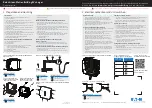
3. Connect the fuse holder to the positive pole of the STARTer
BATTERY
.
4. Connect the other end of the fuse holder to Pin N°3 of the
power
service
.
5. Insert a 70A fuse into the fuse holder
.
6. Connect the negative terminal of the service battery to Pin
No. 2 of the
power
service
.
7. Disconnect all the cables on the positive pole of the service
battery and connect them to pin N°5 of the
power
service
(Not valid for models plus 12-24 and gold 12-24)
8. Connect the service battery positive pole to Pin N°6 of the
power
service
9. connect the D+ OR I SIGNAL WIRE to the
power
service
Pin n°4.
10. only for Gold models: connect the 230VAc mains supply to the
input iec connector. link the connection after the general
system safety switch (rcd switch).
to avoid interferences in audio / video systems:
•
use high quality (and in good condition) cables for TV
antennas and other transceivers.
•
make sure that the
power
service
’s power cables (input and
output) are far from transceivers cables, sensitive devices
power cables and
ac
current cables.
•
Place sensitive equipment as far as possible from the
power
service
.
17
NOTe
•
the data connector placed on the right of the power
connector is for
technical use
.
it is strictly forbidden to
connect any device in this socket, any tampering could
irreparably damage the appliance.
•
use cables with a cross-section of at least 10
mm
2
for:
connections between engine battery and Power Service, and
in the output towards the service battery. if the distance
between the motor battery and the device exceeds 2
meters,
it’s RECOMMENDED to increase the cable section, to reduce
voltage drop and power losses
.
Содержание POWERSERVICE PLUS 25
Страница 42: ...42 V 03 2018...
Страница 43: ...43...


