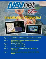
background image

NavNet TZ

touch

 Installation Checklist 


NNTZ

touch

 MFD Network Installation (without NN3D): 


Connect all NNTZ

touch

 MFDs to the Ethernet Network. If a HUB101 is 

used, set the internal HUB DIP switches to OFF (HUB101 DIP Switches 
are OFF by Default).  NNTZ

touch

 MFDs do not use “power-on” 

synchronization. 

Note: If you use the internal HUB of the NNTZT14, realize that the 

HUB will only be able to relay Ethernet traffic when the MFD is turned 

ON. For multi-station network installations, we recommend using an 

external HUB (such as the Furuno HUB101) allowing redundancy in 

case an MFD is powered OFF.


Connect all NNTZ

touch

 MFDs to a proper NMEA2000 backbone using 

drop cables (18 feet or less). 

Note: NNTZtouch MFDs are fully NMEA2000 Certified and do not have 
an internal terminal resistor that can be switched ON or OFF.  All 
connections to the NMEA2000 backbone must be “drop” connections 
(18 feet or less).


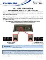
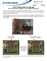
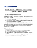
Make sure the DFF1 and DFF3 are set up for “fixed IP addresses” (See 
appendix for more information on setting up both) 


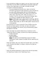
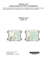
Connect the Radar Ethernet and Power cable to the PSU, then connect 
the second Ethernet port of the PSU to the HUB or directly to the 
TZ

touch

 MFD. Make sure that a jumper is inserted inside the PSU on 

“J7”.  (This allows the PSU to start without a power synchronization 
signal). 

Note:  A sticker 

Optional jumper for TZtouch included” is placed on all 

PSU units that include a jumper for “J7” in the packaging! You MUST 
still open the PSU and insert it. If you are utilizing an existing PSU, just 
order the jumper (part # 001-183-760-00) and insert it on J7 to make 
the PSU compatible with a NNTZtouch network.


Power ON the HUB, the PSU, the NMEA2000 backbone and all the 
sensors, then start the NNTZ

touch

 MFDs. 

Note: During the power ON sequence, the NNTZtouch MFDs display a 
black screen for 10-15 seconds: this is normal. 


Содержание TZtouch

Страница 1: ...N3D Pg 5 MIXED NavNet TZtouch MFD and NavNet 3D MFD Network Installation Pg 6 DFF1 Dip Switch Settings Pg 7 DFF3 Dip Switch Settings Pg 8 PSU 012 013 Jumper Locations for TZT9 14 Installations Pg 9 Ho...

Страница 2: ...F All connections to the NMEA2000 backbone must be drop connections 18 feet or less Make sure the DFF1 and DFF3 are set up for fixed IP addresses See appendix for more information on setting up both C...

Страница 3: ...f you have a DRS with older software please follow the NNTZT DRS Update document found in the appendix Note that there is no need to restart the TZtouch MFDs to have the Sounder and Radar appear in th...

Страница 4: ...Master Device setting from the Initial Setup menu Proceed to the Unit adjustments from the Units menu Proceed to the Time Offset adjustments using the Time Zone drop down of the General menu Note Note...

Страница 5: ...USA will link the NN3D and NNTZT SystemIDs in our www servers This will generate new unlock codes for the NNTZtouch MFDs from the existing NN3D unlock codes This is a free service provided by Furuno...

Страница 6: ...selection for your type of NavNet display To access the dip switches remove the rubber cap on the front of the DFF1 unit DEFAULT settings NavNet 3D ALTERNATE settings NavNet 1 VX2 TZtouch This settin...

Страница 7: ...For connection to NavNet 1 VX2 NN3D TZtouch The DFF3 comes defaulted to work with the NavNet 3D MFDs If you are connecting the DFF3 to an original NavNet NavNet VX2 or TZtouch only system you need to...

Страница 8: ......

Страница 9: ...d in step b and copy it CTRL C e Open the SD Card and Paste the UPLOADER folder to the root of the SD Card CTRL V Note 2 Do NOT copy the files to the root of the SD Card copy the UPLOADER folder to th...

Страница 10: ...s can be done by cutting the power to the PSU or by disconnecting and reconnecting the DRS power cable to the DRS b Wait for 2 minutes c Click Scan on the MFD to refresh the list g Click on Start to b...

Отзывы: