BHM
01/21/15
NTV-DOC156
rB2
Agreement
:
End user agrees to use this product in compliance with all State and Federal laws. NAV-TV Corp. would not be held liable for
misuse of its product. If you do not agree, please discontinue use immediately and return product to place of purchase. This product is
intended for off-road use and passenger entertainment only.
4 |
P a g e
Installation
1.
Remove the factory radio. This normally requires removing trim panels and a series of
screws. Disconnect all harnesses connected to the COMAND radio and set the radio
aside.
2.
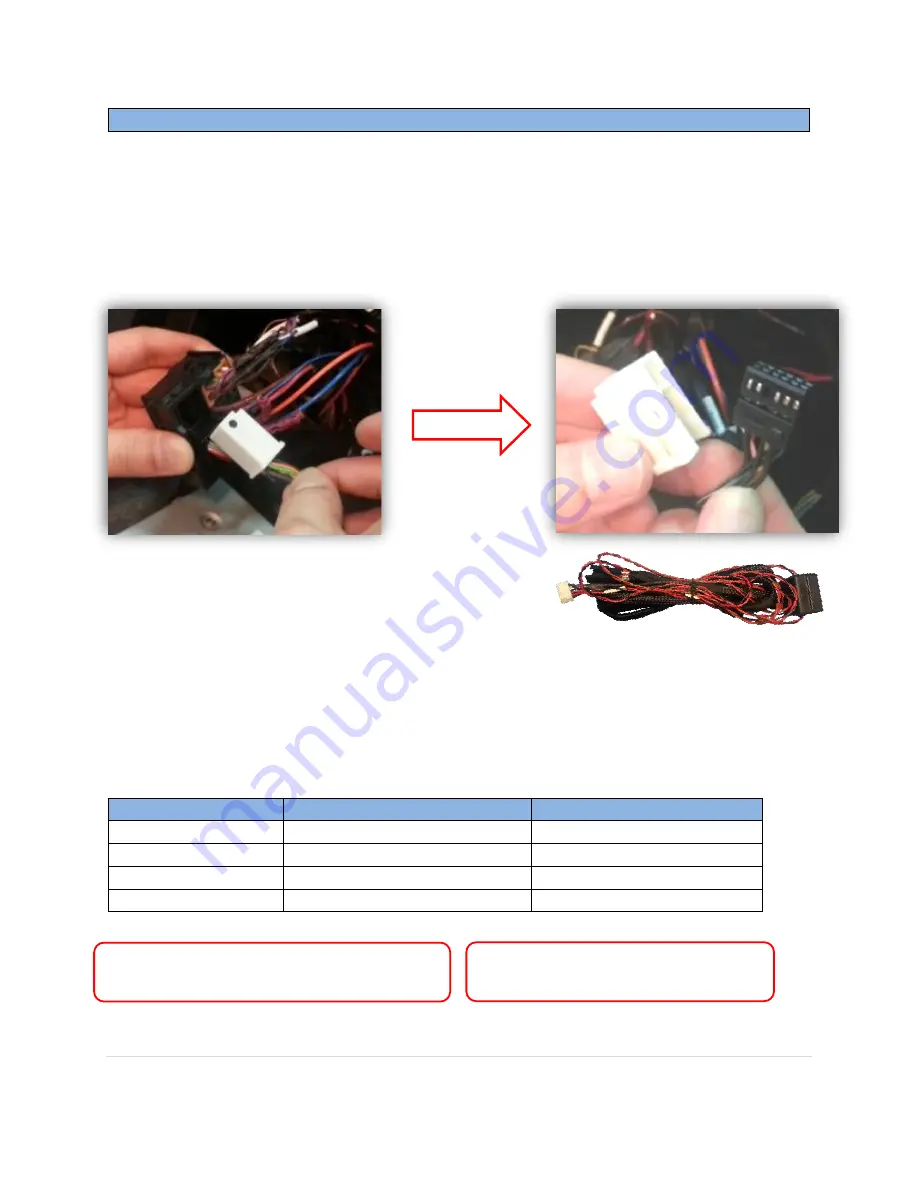
Locate the
white connector
inside the factory 44-pin main COMAND radio plug.
Disconnect the white connector via the retaining clip.
3.
Separate the white cover from the black plug by releasing the clip on the side.
4.
Connect the white cover (removed from step 3) to
the black, male end of the provided
Power/CAN T-
Harness
.
5.
Insert the same connector (from step 4) back into the main factory 44-pin connector
until it clicks into place.
6.
Connect the factory black 12-pin connector (removed from the white clip in step 3) into
the female end of the supplied
Power/CAN T-Harness
.
7.
From the same provided
Power/CAN T-Harness
, locate and solder the following wires to
the car*:
W204-12 Wire Label
Connect to CAR’s
Location
GND (black)
Ground (-)
44-Pin main plug
ACC (red)
Accessory wire (+)
Cigarette lighter
CAN1-L (brown)
CAN-L (Yellow/Brown)
twisted
Pin 9
, 44-Pin main plug
CAN1-H (red)
CAN-H (Yellow/Red)
twisted
Pin 11
, 44-Pin main plug
*Note 2:
Connect the CAN wires behind
the
radio, not at the screen!
*Note 1:
CAN wire color will vary per vehicle,
but they will be twisted.


