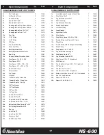
31
63
79
77
65
74
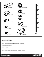
2 3/4"L
2"L
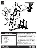
Double Floating Pulley Bracket
4 1/2" Pulley
Cable #1 - Pull Down
Hex Bolt 3/8" x 2 3/4"L
Hex Bolt 3/8" x 2"L
3/8" Flat Washer
3/8" Lock Nut
Step Spacer 5/8"H
B.
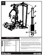
Thread one end of Cable #1 (53) into the Top Weight Assembly as shown in detail A. Do not
tighten locking nut.
C.
Remove the Ball, Washer, and U-Bracket from the other end of Cable #1.
D.
Route Cable #1 (53) over the Pulley located above the weight stack and around a Pulley
installed in a Double Floating Pulley Bracket (31) as shown.
E.
Route Cable #1 (53) over two 4 1/2" Pulleys (44) located on the Top Frame and around a
Pulley installed on a second Double Floating Pulley Bracket (31) as shown. Proceed by
routing the Cable around a 4 1/2" Pulley on the Top Frame.
A.
Attach Three 4 1/2" Pulleys (44) to the brackets located on the Top Frame using the hardware
shown in detail B. Tighten hardware securely.
TM
NS-600
12
Step #7 Materials:
step
7
#
Description
Qty.
2
5
1
2
3
6
5
4
31
44
52
63
65
74
77
79
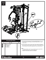
F.
Route Cable #1 around the 4 1/2" Pulley installed in the bracket on the Front Upright and over
the Pulley located just above the bracket. Proceed by routing the cable around the lower
Pulley on the Press Arm Support, around the upper Pulley on the Front Upright, and around
the upper Pulley on the Press Arm Support as shown.
G.
Feed Cable #1 (53) Through the Top Frame tube and out the front slot. Re-install the Ball,
Washer, and U-Bracket to the end of the cable. Make Sure the rubber o-ring is still in its
original position.
53
H.
Loop Cable #1 around a 4 1/2" Pulley (44) and attach it to the Top Frame in Location A using
hardware shown. Proceed by looping the Cable around a 4 1/2" Pulley (44) and attach it to
the Top Frame in Location B using the hardware shown. Make sure the cable is seated properly
in the Pulleys, and tighten hardware securely.
44
A
B
B
A
C
230" (5840mm)
Содержание NS-600
Страница 1: ...TM NS 600 Assembly Instructions Rev B...


