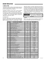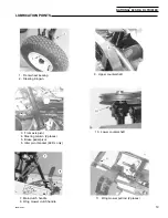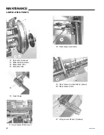
NATIONAL 68 SR & DL TRIPLEX
®
17
68OM-06/03
HEIGHT OF CUT ADJUSTMENT
To assure safety, disengage the
engine clutch lever, remove the
ignition key, and disconnect the engine spark plug
wire prior to making any of the following adjustments.
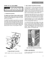
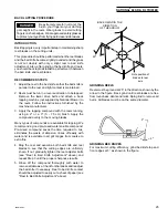
1. STANDARD ADJUSTERS
The height of cut is variable and may be adjusted on both
wing cutting units and the rear cutting unit by loosening
the top and bottom Adjusting Nuts (A) which hold Roller
Adjusters (B) in Roller Brackets (C). Roller (D) may then
be moved up and down.
It is important to get all rollers adjusted to the same height
so that there will be uniform cutting across the entire width
of the cutting unit. Do not adjust by sight. Place the mower
on a hard, level surface and place a board or gauge plate
of the desired height under each bed knife back bar. Allow
the rear roller to rest on the level surface. Retighten the
adjusting nuts and remove the gauge plate or board.
STANDARD HEIGHT ADJUSTER
NOTE: Guards removed or cut away to show detail
For other machine adjustments, see the Maintenance
section of this manual.
DIAL-A-HEIGHT ADJUSTER (OPTIONAL)
2. DIAL-A-HEIGHT ADJUSTERS (OPTIONAL)
To set the height of cut, lift the vinyl cap and socket (A) off
the adjuster tube. To raise the height of cut, turn the
socket clockwise (viewed from above). To lower the
height of cut, turn the socket counterclockwise. Each
quarter turn (90°) of the socket will raise or lower the
height of cut by approximately 1/32". A full turn (360°) will
raise or lower the height of cut approximately 1/8".
When making large adjustments (over 1/2"), make small
adjustments to each side until the desired change is
reached. When the desired height is achieved, lower the
socket and make sure the adjuster tube locks it in position.
The scale decal (C) on the rear side of the adjuster
indicates the height of cut. To use it, sight along the
bottom edge of the adjuster tube (B). The reading on the
scale is your approximate height of cut.
You should determine the exact settings by test mowing
your turf. If very accurate cutting heights are required,
place the cutting units on a hard, level surface and place
a board or other gauge plate of the desired height under
each bed knife backing bar. Lower the rollers to the level
surface. When completed, make sure the socket is
locked in position over the adjuster tube.
OTHER ADJUSTMENTS
DANGER
Содержание 68 DL TRIPLEX
Страница 26: ...68OM 06 03 26 MAINTENANCE RECORD e t a D k s a T e c n a n e t n i a M n o s r e P ...
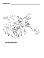
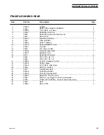
Страница 28: ...68OM 06 03 28 FRAME RUNNING GEAR PARTS LIST ...
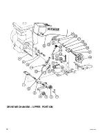
Страница 32: ...68OM 06 03 32 DRIVE MECHANISM UPPER PORTION ...
Страница 36: ...68OM 06 03 36 DRIVE MECHANISM MODEL 68 DL ...
Страница 38: ...68OM 06 03 38 REAR AXLE DIFFERENTIAL ...


