68OM-06/03
12
ASSEMBLY
WARNING
Improper assembly or adjustments
can cause serious injury.
SEAT
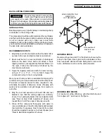
1. Mount the Rear Cutting Unit Lifter and Seat Assembly
(A) to the mower frame using (2) 1/2" bolts, nuts, and
washers (B).
2. Fasten the seat slides (C) to the bottom of the seat (D)
using the fasteners provided with the slider mecha-
nisms. Orient the slider so the adjuster lever (E) is on
the operator's left hand side.
3. Remove the seat switch bracket (F, 1" x 10" bar))
mounted near the ends of the legs of the seat hinge.
Discard the fasteners. Mount the seat and slider as-
sembly onto the seat hinge (G). Replace the seat
switch bracket and tighten fasteners. Plug the wire
harness socket (H) into the seat safety switch (J). Use
care in routing the wires so that they are not pinched
by the switch lever or seat support mechanisms.
REAR CUTTING UNIT
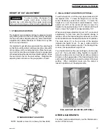
1. Pivot the Seat Brace (A) from the axle so that the top
end aligns with the tab at the back of the seat hinge
assembly. Fasten with a 5/16" x 1" Hex Head Bolt,
Lock Washer and Hex Nut.
2. Slide the rod end of the lifter tee (B) through the hole
(C) in the pad on the rear mower frame and secure it
to the lift arm pivot with the cotter pin and washer as
shown at (D).
3. Attach the Pull Rod (E) to the cutting unit Pivot Tube
(F) with Pin and Spacers.
NOTE: Before completing assembly, it will be necessary
to adjust the drive belt tension. See "Rear Cutting Unit
Drive Belt Tension" in the Maintenance section of this
manual, page 23.
Содержание 68 DL TRIPLEX
Страница 26: ...68OM 06 03 26 MAINTENANCE RECORD e t a D k s a T e c n a n e t n i a M n o s r e P ...
Страница 28: ...68OM 06 03 28 FRAME RUNNING GEAR PARTS LIST ...
Страница 32: ...68OM 06 03 32 DRIVE MECHANISM UPPER PORTION ...
Страница 36: ...68OM 06 03 36 DRIVE MECHANISM MODEL 68 DL ...
Страница 38: ...68OM 06 03 38 REAR AXLE DIFFERENTIAL ...


