NATIONAL 68 SR & DL TRIPLEX
®
15
68OM-06/03
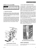
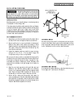
D. Transport Clutch (Model 68 DL only)
NEVER USE THE TRANSPORT
CLUTCH WHILE THE CUTTING
UNITS ARE TURNING OR WHEN THE
DIFFERENTIAL SHIFT IS IN REVERSE.
Use this clutch to travel
between mowing sites at
speeds faster than those
obtained with the main
clutch. Before using,
disengage the cutting unit
clutches and raise the
cutting units to their
transport position.
Operate the transport clutch by slowly pressing the pedal
with your left foot. Releasing the pedal will cause the
mower to coast to a stop, or resume mowing speed.
E.
Wing Cutting Unit Latch
NEVER ATTEMPT TO RAISE THE
WING CUTTING UNITS WHEN
THE WING MOWER CLUTCH IS
ENGAGED.
The Wing Cutting Units should be latched in their elevated
position whenever the mower is being transported or in
storage.
If needed, push the latch
(E) down to a generally
horizontal position. Grasp
the Wing Cutting Unit lift
handle (not shown) and
raise the cutting unit until
the latch (E) engages the
lift arm socket (F).
To release the latch, lift the handle until the latch (E)
swings upward into a nearly vertical position, then carefully
lower the cutting unit onto the ground. Avoid dropping the
cutting unit, as damage may result to the cutting unit, the
mower, or your turf.
OPERATION
G. Rear Cutting Unit Clutch
Engages drive to the Rear
Cutting Unit.
Pull lever forward and
toward the center of the
machine to engage sliding
jaw clutch.
To disengage, pull lever
forward and out to engage
locking pin.
Never engage the drive
unless the rear cutting unit
has been lowered to the
cutting position.
H. Rear Cutting Unit Lift Arm
Raises rear mower to the
transport position. Pull
handle up, forward and
over center to lock it in
the up position.
J. Seat Position Adjuster Lever
DO NOT OPERATE THE SEAT
SLIDE MECHANISM WHILE THE
MOWER IS MOVING
The seat may be moved forward or backward to suit the
operator. Pull the lever near the front left corner of the
seat outward to release the slide mechanism. After
moving the seat to a comfortable position, release the
lever to lock the slide mechanism.
.
WARNING
WARNING
WARNING
Содержание 68 DL TRIPLEX
Страница 26: ...68OM 06 03 26 MAINTENANCE RECORD e t a D k s a T e c n a n e t n i a M n o s r e P ...
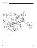
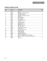
Страница 28: ...68OM 06 03 28 FRAME RUNNING GEAR PARTS LIST ...
Страница 32: ...68OM 06 03 32 DRIVE MECHANISM UPPER PORTION ...
Страница 36: ...68OM 06 03 36 DRIVE MECHANISM MODEL 68 DL ...
Страница 38: ...68OM 06 03 38 REAR AXLE DIFFERENTIAL ...


