Appendix D
Using the Trigger Ports on the NI VXI-8360LT
©
National Instruments
D-3
VXI-MXI-Express Series User Manual
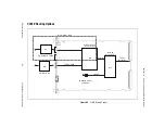
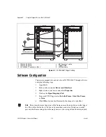
Figure D-1.
Trigger Configuration Sticker
(Located on the Side of the NI VXI-8360LT)
Software controls whether the trigger is routed
In to the Frame
or
Out of
the Frame
.
Triggers are mapped into and out of your NI VXI-8360LT though software
using the following steps.
1.
Open MAX.
2.
Find your device under
Devices and Interfaces
.
3.
Right click on your device and select
Properties
.
4.
Click on the
Signal Mappings Tab
.
5.
For each TTL Trigger select
Into the Frame
,
Out of the Frame
,
or
None
.
6.
Click
OK
and re-run the Resman for the changes to take effect.
HARDWARE
SOFTWARE
Trigger set to:
Into the frame
Trigger set to:
Out of the frame
Receiver
Receiver w/ Bias Device
Wired-Or
Driven
T R I G G E R C O N F I G U R AT I O N
0 1 2 3
4 5 6 7
Trigger Number
Switches shown in
Receiver / Wired-Or
position.
1
2
3
4
1
2
3
4


