


Chapter 4
Register Descriptions
4-4
www.natinst.com
9-8
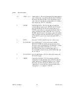
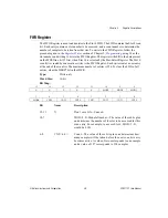
CHAN<1..0>
Channel Select—These bits determine the channel number
(zero to three) that is loaded into the MUXCOUNTER to
determine the analog channel to be read during a single
read, or the starting channel on the module for a scanned
data acquisition. CHAN1 is the MSB.
5
RTEMP
Read Temperature—This bit determines whether the
selected channel output or the MTEMP signal is driven
onto the MCH0± pins of the rear signal connector. If
RTEMP is cleared to zero, the selected channel output is
used as the module output. If RTEMP is set to one, the
MTEMP signal is used as the module output. The module
output will only be driven when FOUTEN* is cleared to 0,
or SCANCON is active (low) while SCANCONEN* is
cleared.
4
RSVD
Reserved—This bit should always be written to zero.
3
SCANCLKEN
Scan Clock Enable—This bit determines whether
MUXCOUNTER will increment on each clock signal
(the clock source is determined by CLKSELECT), or keep
its loaded value. If SCANCLKEN is set to one,
MUXCOUNTER will be clocked during scans. If
SCANCLKEN is cleared to zero, MUXCOUNTER will
not be clocked.
2
SCANCONEN
Scan Control Enable—This bit, when high, enables the
SCANCON signal.
1
AB0EN
Analog Bus 0 Enable—This bit determines whether
Analog Bus 0 on the SCXIbus drives MCH0 on the rear
signal connector. If AB0EN is cleared to zero, Analog
Bus 0 does not drive MCH0. If AB0EN is set to one,
Analog Bus 0 + drives MCH0+ through a buffer and a
Analog Bus 0 – is connected to MCH0–.


