


Appendix E
SCXI-1121 Cabling
©
National Instruments Corporation
E-3
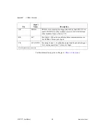
No other pins are connected on the SCXI-1121.
SCXI-1340 Installation
Follow these steps to install the SCXI-1340:
1.
Make sure that the computer and the SCXI chassis are turned off.
2.
Install the SCXI module in the chassis.
3.
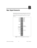
Plug the mounting bracket connector onto the module rear signal
connector (see Figure E-1). Make sure the alignment tab on the bracket
enters the upper board guide of the chassis.
4.
Screw the mounting bracket to the threaded strips in the rear of the
chassis.
5.
Connect the loose end of the cable assembly to the MIO-16 board rear
signal connector.
Check the installation.
After step 1, the order of these steps is not critical however, it is easier to
locate the correct position for the mounting bracket with a module installed
in the chassis. If you will attach a cable to the breakout connector,
installation is easiest if you attach the second cable before installing the
SCXI-1340.
25
SERDATIN
ADIO0
26
SERDATOUT
BDIO0
27
DAQD*/A
ADIO1
29
SLOT0SEL*
ADIO2
36
SCANCLK
SCANCLK
37
SERCLK
EXTSTROBE*
43
RSVD
OUT1
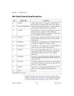
Table E-1.
SCXI-1121 and MIO-16 Pinout Equivalences (Continued)
Pin
SCXI-1121 Rear
Signal Connector
MIO-16 Equivalent


