


Appendix C
SCXIbus Connector
©
National Instruments Corporation
C-3
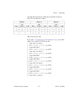
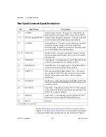
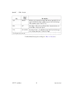
SCXIbus Connector Signal Descriptions
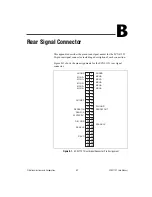
Pin
Signal
Name
Description
A1, B1, C1, D1,
A2, D2,A3, B3,
C3, D3, A4, D4,
A5, B5, C5, D5,
A6, D6
GUARD
Guard—Shields and guards the analog bus lines from noise.
B2
AB0+
Analog Bus 0+ —Positive analog bus 0 line. Used to multiplex
several modules to one analog signal.
C2
AB0–
Analog Bus 0– —Negative analog bus 0 line. Used to multiplex
several modules to one analog signal.
C13-C17, A21,
B21, C21, D21
CHSGND
Chassis Ground—Digital and analog ground reference.
C18
RSVD
Reserved.
A19
RESET*
Reset—When pulled low, reinitializes the module to its power-up
state. Totem pole. Input.
B19
MISO
Master-In Slave-Out—Transmits data from the module to the
SCXIbus. Open collector. I/O.
C19
D*/A
Data/Address—Indicates to the module whether address
information or data information is being sent to the module on
MOSI. Open collector. I/O.
D19
INTR*
Interrupt—Active low. Causes data that is on MOSI to be written
to the Slot-Select Register in Slot 0. Open collector. Output.
A20, B20, C20,
D20
V–
Negative Analog Supply— –18.5 to –25 V.
A22, B22, C22,
D22
V+
Positive Analog Supply— +18.5 to +25 V.
A23, D23
+5 V
+5 VDC Source—Digital power supply.
B23
SPICLK
Serial Peripheral Interface (SPI) Clock—Clocks the serial data
on the MOSI and MISO lines. Open collector. I/O.
C23
MOSI
Master-Out Slave-In—Transmits data from the SCXIbus to the
module. Open collector. I/O.


