©
National Instruments Corporation
17
18-Slot NI PXIe-1065 Backplane Installation Guide
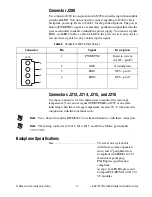
Connector J200
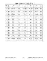
Use connector J200 in conjunction with J205 for interfacing with an inhibit
switch and LED. You do not need to connect anything to J200 for basic
backplane power up. Refer to Table 3 for the pin descriptions. The power
button (PWRBTN#) signal is a momentary pushbutton signal that tells the
system controller to enable or inhibit the power supply. You can use signals
LED1 and LED2 to drive a bicolor LED in the power switch, but you also
can use these signals to carry another digital signal.
Connectors J213, J214, J215, and J216
Use these connectors for four thermistors to monitor the card-cage
temperature. You can use signal OVERTEMP# on J205 as an alarm
indicating when the card-cage temperature exceeds 90 °C when used in
conjunction with the four thermistors.
Note
Use a Sensor Scientific KWM502C-6 or similar thermistor with these connectors.
Note
The mating connector for J213, J214, J215, and J216 is Molex part number
50-57-9402.
Backplane Specifications
Size......................................................... 3U-sized; one system slot
(with three system expansion
slots) and 17 peripheral slots.
Compliant with IEEE 1101.10
mechanical packaging.
PXI Express specification
compliant.
Accepts both PXI Express and
CompactPCI (PICMG 2.0 R 3.0)
3U modules.
Table 3.
Connector J200 Pin Descriptions
Connector
Pin
Signal
Description
1
PWRBTN#
Input to system
slot J20—pin F2
2
GND
Ground plane
3
LED1
J205—pin 16
4
LED2
J205—pin 17
1
2
3
4
J200


