


©
National Instruments Corporation
11
18-Slot NI PXIe-1065 Backplane Installation Guide
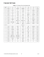
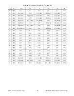
The system timing slot has a control pin for PXIe_SYNC100 called
PXIe_SYNC_CTRL, for use when
n
> 1. Refer to Table 10,
XP3 Connector
Pinout for the System Timing Slot
, for the system timing slot pinout. Refer
to
Backplane Specifications
for the PXIe_SYNC_CTRL input
specifications.
By default, a high level detected by the backplane on the
PXIe_SYNC_CTRL pin causes a synchronous restart for the
PXIe_SYNC100 signal. On the next PXI_CLK10 edge, the
PXIe_SYNC100 signal restarts. This allows several chassis to have their
PXIe_SYNC100 in phase with each other. Refer to Figure 6 for timing
details with this method.
Figure 6.
PXIe_SYNC100 at 3.33 MHz Using PXIe_SYNC_CTRL as Restart
Mechanical Requirements
Mounting
Figure 7 shows the backplane dimensions. There are 42 holes available for
mounting with M2.5 hardware.
Use all mounting holes for proper backplane support.
Five mounting holes on top of the backplane have plated annular pads on
the front and back of the backplane. Use these mounting holes to connect
the backplane ground to the chassis in which the backplane is mounted. If
you do not want to connect the backplane ground to the chassis, use
insulated washers at these mounting holes. Refer to Figure 9 for the
mounting hole positions.
Cooling
Note
National Instruments is not responsible for damage to the backplane if inadequate
cooling is used.
You should mount a fan below the backplane. Airflow should be from the
bottom to the top of the PXI modules. You must determine the airflow
requirements for your system based on the
PXI Hardware Specification
.
PXI_CLK10
PXIe_SYNC_CTRL
PXIe_SYNC100
SYNC100 Divider
Restarted Here


