© National Instruments
|
4-7
Connecting an External Lighting Controller to the
NI Smart Camera
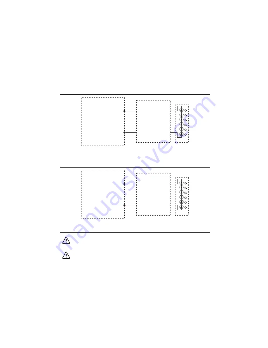
Figure 4-2 illustrates how to connect an external lighting controller to the 5 V TTL output on the
NI Smart Camera.
Figure 4-2.
Connecting an External Lighting Controller to the 5 V TTL Strobe Output
Figure 4-3 illustrates how to connect an external lighting controller to the 24 V output on the NI
Smart Camera.
Figure 4-3.
Connecting an External Lighting Controller to the 24 V Strobe Output
Isolated Inputs
Caution
Do
not
apply a voltage greater than 30 VDC to the isolated inputs.
Voltages greater than 30 VDC may damage the NI Smart Camera.
Caution
The isolated inputs and outputs on the smart camera provide an easy
means for preventing ground loops that could degrade signal integrity. The isolation
on the smart camera is
not
safety isolation.
5 V TTL
S
tro
b
e O
u
tp
u
t
GND O
u
tp
u
t
LED
Extern
a
l
Lighting
Controller
NI 17xx
24 V
S
tro
b
e O
u
tp
u
t
(~ 1
8
V –
3
0 V)
GND O
u
tp
u
t
Extern
a
l
Lighting
Controller
NI 17xx
LED
Содержание NI Vision 17 Series
Страница 1: ...ISC 1752...


