background image

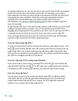
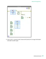
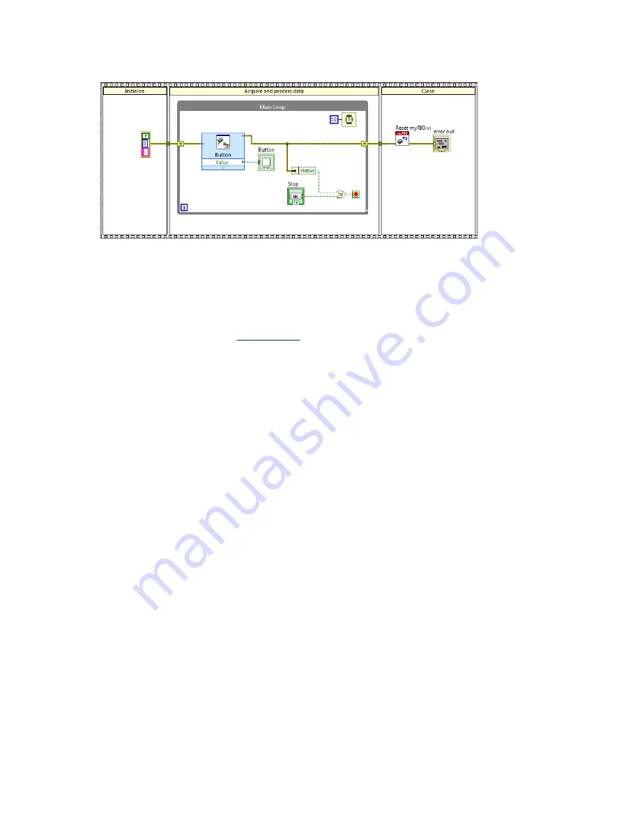
The block diagram contains the graphical code of a VI. The Main VI contains a

Button Express VI which reads the Boolean value from the user programmable

button and displays the changes of the Boolean values in the LED on the front

panel. The Main VI uses a Flat Sequence structure that contains several

subdiagrams. Refer t

Structures

 for more information about the structure of

the Main VI.

3.  Select 

View

 » 

Functions Palette

 to display the Functions palette. You can

also right-click on the block diagram to display the palette. Navigate to

Functions

 » 

Academic I/O

 » 

Control I/O

 to locate the LED Express VI.

4.  Drop the LED Express VI in the Main Loop of the Main VI by clicking the LED

Express VI and then clicking on the block diagram.

ni.com

30

NI ELVIS III Getting Started

Содержание NI ELVIS III

Страница 1: ...NI ELVIS III Getting Started 2023 09 18...

Страница 2: ...ting the Device to Your Host Computer 8 Configuring the Device 14 Setting up the Host Computer 19 Installing the Measurements Live Support Files 20 Installing the NI ELVIS III Software Bundle 20 Using...

Страница 3: ...ur lab administrator has not set up the hardware and software for you set up your device and the host computer first Lab administrator Guide for Lab Administrators Instructs you to set up lab devices...

Страница 4: ...bling and sensors as required for your application Wire cutter Wire stripper Software NI ELVIS III Software Bundle Installer optional Documentation NI ELVIS III Quick Start Guide NI ELVIS III Safety E...

Страница 5: ...efore you set up and use the NI ELVIS III device ensure that you have the required items listed in the What You Need to Get Started section 1 Ensure that the power switch at the back of the NI ELVIS I...

Страница 6: ...wall outlet and switch on the power switch at the back of the NI ELVIS III workstation 5 Ensure that the application board power button on the workstation is turned off The integrated LED in the powe...

Страница 7: ...b Slide the edge connector of the NI ELVIS III prototyping board into the receptacle on the workstation and ease it into place 7 Secure the NI ELVIS III prototyping board to the workstation using two...

Страница 8: ...cation between the devices connected to the Measurements Live network and the instrument soft front panels in Measurements Live access to which is provided with the product NI does not store or use th...

Страница 9: ...f the USB cable to the host computer Notice Ensure that the host computer is powered on before connecting the USB cable If the connection is successful you can see the IP address of the USB connection...

Страница 10: ...e Device if you need to upgrade the software on the device or set up an administrator password Connecting to the Device via Ethernet Complete the following steps to use an Ethernet cable to connect th...

Страница 11: ...il you turn on the display The IP address of the Ethernet connection appears after the icon Tip Go to Setting up the Host Computer to set up the software environment Tip Go to Configuring the Device i...

Страница 12: ...to before 1 Use a USB cable to connect the NI ELVIS III to your computer as explained in Connecting to the Device via USB 2 In Internet Explorer enter http USB IP address WIF html in the address bar...

Страница 13: ...wn menu You must specify a country before you can select an available channel for the wireless network 6 Select the wireless network you want to join or select Other network if you cannot find the wir...

Страница 14: ...able button on the left hand side of the NI ELVIS III workstation until you turn on the display The IP address of the wireless network connection appears after the icon Tip Go to Setting up the Host C...

Страница 15: ...ow to upgrade the firmware on the NI ELVIS III Securing the Device This topic tells you how to protect your lab devices by setting administrator password and permissions For more information about con...

Страница 16: ...ected where x matches the version of the LabVIEW ELVIS III Toolkit 6 Click Next to view a summary of your selection 7 Click Next to start installing the software When the installation completes the wi...

Страница 17: ...the firmware Note If MAX prompts you to log in enter admin in User name and leave Password blank if you have not set a new password Refer to Securing the Device to learn how to set a new password for...

Страница 18: ...Login with the default user name and password a Click Log In on the toolbar b Enter admin in User name and leave Password blank c Click OK 3 Click Set Permissions on the toolbar to launch the Security...

Страница 19: ...ng permissions section and click Remove to remove all the permissions 6 Click Save to save the change Tip Go to Setting up the Host Computer next Setting up the Host Computer According to the task you...

Страница 20: ...host computer navigate to the icon that represents the NI ELVIS III USB drive 3 Open Start Here html and follow the instructions on the screen to install the Measurements Live Support Files You can n...

Страница 21: ...the Device This section provides step by step instructions on how to access and control the instruments on the NI ELVIS III by using the Soft Front Panels SFPs and how to program the I O on the NI EL...

Страница 22: ...ollowing sections to find answers to commonly raised questions How Do I Rearrange My SFPs You can rearrange the SFPs within the browser window to get a better layout Click the icon on the top left sid...

Страница 23: ...Oscilloscope to generate and display a waveform 1 Connect a BNC BNC cable between the Oscilloscope CH 1 and the Function Generator CH 1 BNC connectors on the NI ELVIS III as shown in the following dia...

Страница 24: ...to start the Oscilloscope You should see a 100 Hz sine wave on the Oscilloscope display Adjust the settings of the FGen Arb and observe the changes of the waveform on the Oscilloscope display User Pr...

Страница 25: ...rrent state using a Boolean indicator When you press the button the Boolean indicator of the VI returns TRUE Note Take care when you press and hold the user programmable button to display the device I...

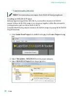
Страница 26: ...project you can group together all the files relevant to your application and run VIs on the NI ELVIS III Complete the following steps to create an NI ELVIS III project by using the NI ELVIS III Proj...

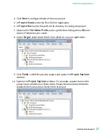
Страница 27: ...s different copies of templates you create 8 Under Target select the NI ELVIS III on which to run your application 9 Click Finish LabVIEW saves the project and opens the Project Explorer window 10 Exp...

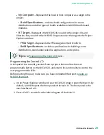
Страница 28: ...hows the Project Explorer window when you add the NI ELVIS III and its chassis to a LabVIEW project To add a chassis right click the NI ELVIS III target in the Project Explorer window and select New T...

Страница 29: ...distributions stand alone real time applications and zip files Tip Go to Programming the Control I O next Programming the Control I O In this part of the tutorial you start from a project that monito...

Страница 30: ...contains several subdiagrams Refer to Structures for more information about the structure of the Main VI 3 Select View Functions Palette to display the Functions palette You can also right click on t...

Страница 31: ...ve the cursor over options in the configuration dialog box and learn basic information about the options from the Context Help window Most objects in LabVIEW display context help information 6 Select...

Страница 32: ...nd select Create Control to create Boolean controls for the LEDs You can click a Boolean control on the front panel to toggle between the TRUE and FALSE states which determines the ON and OFF states o...

Страница 33: ...8 Press Ctrl E to switch to the front panel of the Main VI Arrange the Boolean controls from left to right National Instruments 33 NI ELVIS III Getting Started...

Страница 34: ...me time understanding the following LabVIEW programming concepts Structures Error Checking Structures Structures are graphical representations of the loops and case statements of text based programmin...

Страница 35: ...nels on the NI ELVIS III before the application exits You can also use this frame to close user interface elements and variables Tip Go to Error Checking next Error Checking Error checking identifies...

Страница 36: ...hlighted in the figure returns the status element in the error cluster If the Button Express VI returns an error status is TRUE and the Boolean value is passed to the Conditional Terminal also highlig...

Страница 37: ...access the Merge Errors function by navigating to Functions Programming Dialog User Interface Merge Errors The following figure shows the block diagram after you add the Merge Errors function which is...

Отзывы: