background image

4

|

ni.com

|

Getting Started with NI 9501 Modules and NI SoftMotion 

NI SoftMotion Module Overview

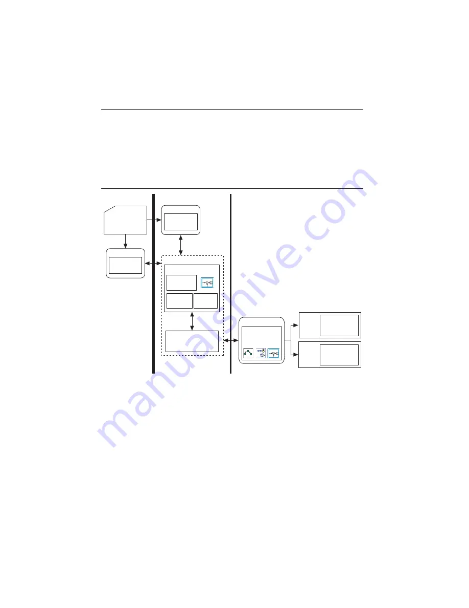
NI SoftMotion Module UDV axes allow you to implement an interface for communication 
between the NI SoftMotion Engine and the LabVIEW FPGA Module. This is achieved using 
user-defined variables that you add to the project, making it easier to use C Series modules in 
FPGA mode with the NI SoftMotion Module. 

The following figure shows the NI SoftMotion architecture when you use the NI SoftMotion 
Module with UDV axes and the LabVIEW FPGA Module.

Figure 2.  

NI SoftMotion Module with UDV Axes

You use the LabVIEW Project to configure your axis settings and test your configuration. When 
your hardware configuration is complete, you use NI SoftMotion APIs to create move profiles. 

Communication to the LabVIEW FPGA Module is handled through user-defined variables. You 
use the NI SoftMotion Drive Interface VIs to implement an interface for communication 
between the NI SoftMotion Engine and the LabVIEW FPGA Module. When you use the Drive 
Interface VIs with UDV axes you communicate using a predefined set of UDVs. Refer to 

Adding 

User-Defined Variables for Use With a UDV Axis

 in the 

NI SoftMotion Module Help, 

available 

by selecting 

Help»LabVIEW Help

 for information about the predefined UDVs. Refer to the 

Using NI 9501 with NI SoftMotion

 section for more information about the NI SoftMotion Drive 

Interface VIs.

Axi

s

Interf

a

ce

Tr

a

jectory

Gener

a

tor

Su

pervi

s

ory

Control

Ho

s

t HMI 

a

nd

Axi

s


S

etting

s

:

L

a

bVIEW Project

Non Real-Time

LabVIEW Real-Time Module

NI SoftMotion

U

s

er VI

NI 

S

oftMotion 

API

s

LabVIEW FPGA with 
NI Scan En

g

ine Supported Platform

S

erie

s


Mod

u

le(

s

)

cRIO 

Ch

ass

i

s

Motor Control, 

Drive Interf

a

ce,

a

nd 

S

ync VI

s

cRIO

Ch

ass

i

s

NI 950x

S

erie

s


Mod

u

le(

s

)

U

s

er-Defined V

a

ri

a

ble

Comm

u

nic

a

tion

Mod

u

le

U

s

er VI

NI 

S

oftMotion 

API

s

U

s

er VI

NI 

S

oftMotion Engine

Содержание 9501 C Series

Страница 1: ...for assistance Contents What You Need to Get Started 2 Hardware 2 Software 3 NI SoftMotion Module Overview 4 Hardware and Software Installation 5 Step 1 Set Up the CompactRIO System 5 Step 2 Connect NI 9501 to the Stepper Motor 6 Step 3 Connect the NI 9501 to the NI PS 16 Power Supply 7 Step 4 Connect the System to AC Power 7 Step 5 Install Software on and Configure the NI RT Controller 7 Using NI...

Страница 2: ...sideration Using the NI C Series Drive Modules at zone ni com for more information Ethernet connection and cable for the CompactRIO controller NI or third party stepper motor Note NI offers NEMA 17 and NEMA 23 stepper motors compatible with the NI 9501 Go to ni com for more information Optional Hardware NI or third party encoder Note NI offers encoders for NEMA 23 stepper motors Go to ni com for m...

Страница 3: ...2 SP1 FPGA Module or later LabVIEW 2012 SP1 NI SoftMotion Module or later NI RIO Device Drivers 2012 or later Figure 1 shows the system setup without optional hardware The Setting Up and Using Optional Hardware section discusses optional hardware including a connection diagram and example walkthrough of optional functionality Figure 1 NI SoftMotion Module with NI 9501 UDV Axis System Overview Ethe...

Страница 4: ...rough user defined variables You use the NI SoftMotion Drive Interface VIs to implement an interface for communication between the NI SoftMotion Engine and the LabVIEW FPGA Module When you use the Drive Interface VIs with UDV axes you communicate using a predefined set of UDVs Refer to Adding User Defined Variables for Use With a UDV Axis in the NI SoftMotion Module Help available by selecting Hel...

Страница 5: ...ctRIO hardware 1 Install the real time CompactRIO controller on the chassis if you are not using an integrated controller and chassis Note Write down the controller serial number before installing the controller onto the chassis You will be unable to read the serial number after you install the controller a Make sure that no power is connected to the controller or the chassis b Align the controlle...

Страница 6: ... NI 9501 module in slot 1 of the chassis if available Note The NI 9501 example programs are configured for slot 1 If the NI 9501 module is installed in a different slot modify the examples accordingly Step 2 Connect NI 9501 to the Stepper Motor 1 Connect the stepper motor to the NI 9501 Figure 4 shows a typical bipolar stepper motor connection Refer to the NI 9501 Operating Instructions and Specif...

Страница 7: ...r power supply to AC power 2 Connect the NI 9501 power supply to AC power Step 5 Install Software on and Configure the NI RT Controller This step covers installing and configuring the software for the NI 9501 stepper drive module It assumes that all required software from the What You Need to Get Started section is installed on the host machine Complete the following steps to configure the control...

Страница 8: ...ing the disk set the Safe Mode switch to the Off position if necessary and click OK in the confirmation dialog box 12 Select the System Settings tab on the bottom and type a descriptive name for the system in the Hostname field 13 Optional Complete this step only if the target has an empty IP address 0 0 0 0 Select the Network Settings tab and select DHCP or Link Local from the Configure IPv4 Addr...

Страница 9: ... Right click the RTTarget item in the Project Explorer window and select Properties from the shortcut menu to open the real time target properties dialog box 3 On the General page enter the IP address you configured in Step 4 Connect the System to AC Power 4 Click OK 5 Right click the target and select Connect from the shortcut menu The RT target icon in the Project Explorer window changes to indi...

Страница 10: ...bout each UDV Table 1 Stepper Drive Getting Started UDV Descriptions UDV Name Description Axis 1 Control Register Contains information used to control the state and operating mode of the device Axis 1 Mailbox FPGA to Host Contains information used to provide configuration and other data from FPGA to the NI SoftMotion Engine Axis 1 Mailbox Host to FPGA Contains information used to provide configura...

Страница 11: ...g Loop The Fault Monitoring loop sends fault information including user defined faults to the NI SoftMotion engine and sends the state machine implemented in the Control Status Loop into a fault state Figure 7 shows the Fault Monitoring Loop from the Stepper Drive Getting Started example Figure 7 Stepper Drive Getting Started Fault Monitoring Loop Axis 1 Status Register Contains information used t...

Страница 12: ...hanges executes the appropriate action on a state change and generates the Status Register UDV that returns information to the NI SoftMotion Engine Review the operations that occur at each transition inside the State Change Case structure The Interpret Control Register and Generate Status Register topics in the NI SoftMotion Help describe the valid state transitions and which operations should occ...

Страница 13: ...ox FPGA to Host and Axis 1 Mailbox Host to FPGA UDVs are used in the Mailbox Loop Figure 10 shows the Mailbox Loop from the Stepper Drive Getting Started example Figure 10 Stepper Drive Getting Started Mailbox Loop The Mailbox Loop transfers axis configuration and other data between the NI SoftMotion Engine and the LabVIEW FPGA Module The transferred data is written to FPGA memory and accessed usi...

Страница 14: ...ed in the Position Loop Figure 12 shows the Position Loop from the Stepper Drive Getting Started example Figure 12 Stepper Drive Getting Started Position Loop The Position Loop receives position setpoints from the NI SoftMotion trajectory generator and uses the Spline Interpolation VI to generate intermediate setpoints resulting in smoother motion The Position Loop receives input from the Synchron...

Страница 15: ...an be sent to the NI SoftMotion Engine Compile and Run the Example Complete the following steps to compile and run the example 1 Right click the axis in the Project Explorer window and select Properties from the shortcut menu to open the Axis Configuration dialog box The Axis Configuration dialog box includes configuration options for stepper drive command signals feedback devices motion and digit...

Страница 16: ...ton and set the Rated Phase Current to the appropriate value for your motor in Amps Phase Use the motor datasheet and the type of motor connection used to determine this setting based on the following table 3 Click OK to close the Axis Configuration dialog box 4 Right click the Chassis item in the Project Explorer window and select Deploy from the shortcut menu Table 2 NI 9501 Rated Phase Current ...

Страница 17: ...d arrow to indicate that the VI is running If the VI is not running press the Run button 7 Right click the axis in the Project Explorer window and select Interactive Test Panel from the shortcut menu Tip Click the Help button on the bottom of the dialog box for detailed information about the items available in this dialog box 8 Click the Enable button on the bottom of the dialog box to enable the ...

Страница 18: ...s the additional modules and what they are used for in the Stepper Drive with Encoder example Table 3 Additional C Series Modules Used in the Stepper Drive with Encoder Example C Series Module Slot Number Purpose NI 9423 Sinking Digital Input Module 2 Limits Home and Digital Inputs NI 9472 Sourcing Digital Output Module 3 Digital Outputs NI9401High SpeedBidirectional Module 4 Position Compare and ...

Страница 19: ...stall and connect an NI 9472 digital output module in slot 3 of the chassis 2 Connect digital output devices to the NI 9472 3 Connect the NI 9472 to the NI PS 16 power supply a Connect an available NI 9472 Vsup terminal to one of the two terminals on the NI PS 16 b Connect an available NI 9472 COM terminal to one of the two terminals on the NI PS 16 Table 4 NI 9411 Limit and Home Connections NI 94...

Страница 20: ...also provides a 5 V supply for encoder power The Stepper Drive with Encoder example uses the following NI 9411 signals for the corresponding encoder signals 3 Connect the NI 9411 to the NI PS 16 power supply a Connect the NI 9411 Vsup terminal to one of the two terminals on the NI PS 16 b Connect the NI 9411 COM terminal to one of the two terminals on the NI PS 16 Table 6 NI 9401 Position Capture ...

Страница 21: ...al inputs 0 through 3 Axis 1 DIO Control Port B Contains the values of digital outputs 4 through 7 as well as information to enable position compare and position capture operations and clear input latches for digital inputs 4 through 7 Note Because the same digital input module is used for digital inputs and for home and limit connections the Stepper Drive with Encoder example only uses digital in...

Страница 22: ...tes interpolated positions filters the encoder velocity using the user specified filter settings and returns the feedback position and filtered velocity feedback information to the NI SoftMotion Engine 1 NI SoftMotion Scan Loop Timer VI 2 Encoder Configuration Information from NI SoftMotion 3 Axis 1 Position Setpoint UDV 4 FPGA Butterworth Filter VI 5 Spline Interpolation Motor Control VI 6 Axis 1...

Страница 23: ...The encoder loop uses the signals from the NI 9411 module to generate position and velocity feedback Position Capture operations are included in the encoder loop to perform the Index capture operation for use with the NI SoftMotion Find Index routine 1 Encoder Configuration Information from NI SoftMotion 2 Encoder Input Signals 3 Incremental Encoder Decoder Motion Control VI 4 Position Capture Mot...

Страница 24: ...ward Limit Reverse Limit Home Switch and Digital Inputs 0 though 3 from the NI 9423 C Series module and Digital Outputs 0 through 3 that are sent to the NI 9472 C Series module 1 Axis 1 DIO Control Port A 2 DIO Port A Configuration Information from NI SoftMotion 3 Limit Home and Digital Input 0 through 3 Signals 4 Interpret DIO Control Port A Drive Interface VI 5 Digital Filter Motor Control VI 6 ...

Страница 25: ...ted Phase Current setting is set to the appropriate value for your motor in Amps Phase Refer to Table 2 for information about how to determine this value Complete the following steps to correct the setting 1 Set the Rated Phase Current in the Axis Configuration dialog box and click OK when you are done 2 Right click the axis in the Project Explorer window and select Deploy from the shortcut menu t...

Страница 26: ...abVIEW select Help LabVIEW Help then expand the LabVIEW NI SoftMotion Module book on the Contents tab LabVIEW Help Use the LabVIEW Help to access information about LabVIEW programming concepts step by step instructions for using LabVIEW and reference information about LabVIEW VIs functions palettes menus tools properties methods events dialog boxes and so on The LabVIEW Help also lists the LabVIEW...

Страница 27: ...esources to email and phone assistance from NI Application Engineers Visit ni com services for NI Factory Installation Services repairs extended warranty calibration and other services Visit ni com register to register your National Instruments product Product registration facilitates technical support and ensures that you receive important information updates from NI A Declaration of Conformity D...

Отзывы: