


12
|
ni.com
|
Getting Started with NI 9501 Modules and NI SoftMotion
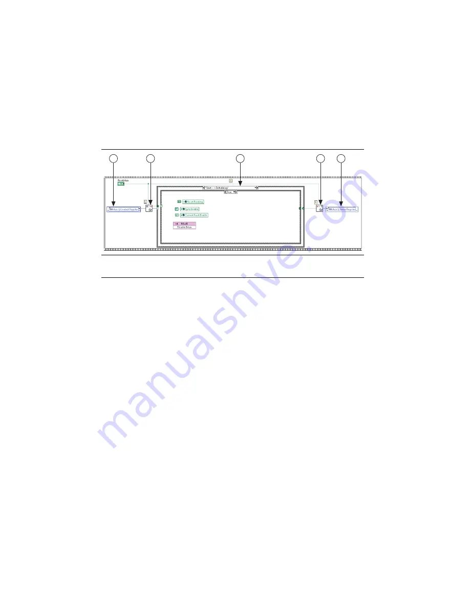
Control Status Loop
The Axis 1.Control Register and Axis 1.Status Register UDVs are used in the Control Status
Loop. Figure 8 shows the Control Status Loop from the Stepper Drive (Getting Started)
example.
Figure 8.
Stepper Drive (Getting Started) Control Status Loop
The Control Status Loop interprets the Control Register UDV and recognizes state changes,
executes the appropriate action on a state change, and generates the Status Register UDV that
returns information to the NI SoftMotion Engine.
Review the operations that occur at each transition inside the State Change Case structure. The
Interpret Control Register
and
Generate Status Register
topics in the
NI SoftMotion Help
describe the valid state transitions and which operations should occur in each state.
1
Axis 1.Control Register UDV
2
Interpret Control Register Drive Interface VI
3
State Change Case Structure
4
Generate Status Register Drive Interface VI
5
Axis 1.Status Register UDV
1
2
3
4
5


