


©
National Instruments Corporation
17
NI 9219 Calibration Procedure
13. Compare the calculation result to the Upper Limit and Lower Limit values in Table 17.
14. Clear the acquisition.
15. Disconnect the resistor from the device.
16. Repeat steps 1 through 15 for all test points and channels on the NI 9219. NI recommends that you
verify the values for all the iterations listed in Table 17 for each channel, but you can save time by
verifying only the values and channels used in your application.
3-Wire RTD Accuracy Verification
Complete the following steps to verify the 3-Wire RTD accuracy of an NI 9219.
1.
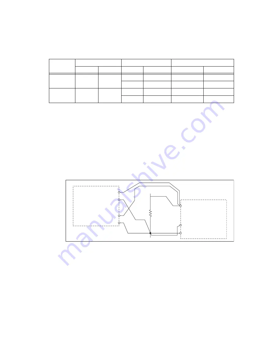
Connect the NI 9219 to the resistor and the DMM as shown in Figure 9. Connect the
HI
and
senseHI
leads of the DMM directly to the spring-terminal connector of the NI 9219 and the
LO
and the
senseLO
leads of the DMM as close as possible to the same point where the LO lead from
the NI 9219 connects to the resistor to ensure that the DMM reference measurements include the
same lead wire resistance as the NI 9219 3-wire measurements.
Figure 9.
3-Wire RTD Accuracy Verification Connections to the NI 9219
2.
Create an AI voltage channel in the 1 V range on the NI 9219.
3.
Commit the task to place the NI 9219 in voltage mode. This prevents the module from interfering
with the resistance measurements of the DMM.
4.
Configure the DMM for a 4-wire resistance measurement in the appropriate range according to the
test point from Table 19.
5.
Enable Auto Zero on the DMM.
6.
Acquire a resistance reading with the DMM. Record this measurement as
TopHalfDMM
.
Table 17.
NI 9219 Verification Test Limits for 4-Wire RTD Accuracy
Mode
Range
Test Point
1
–
Year Limits
Min (
)
Max (
)
Location
Value
Lower Limit (
)
Upper Limit (
)
4–Wire RTD
Pt1000
0
5050
Max
4020
±1%
–3.73
3.73
Min
20
±5%
–0.61
0.61
4–Wire RTD
Pt100
0
505
Max
402
±1%
–0.79
0.79
Min
4.99
±5%
–0.48
0.48
R
TestPoint
NI 9219
Ω
HI
LO
DMM
Ω
SENSE
HI
LO
EX+ (3)
LO (6)
EX– (5)
Ch
x


