5 3/4"
28 3/16”
15 27/32”
5 1/2"
Sealing of the Unit
Water
Water is drained from the unit from channels and weep holes built into the unit itself.
Different gaskets and seals are installed in the unit from the factory. The unit is designed
to take on water from the outside of the unit mounted 3/4” passed the outside wall.
The water is directed thru weep holes so it can exit the unit
. Gaskets are installed
around equipment to help manage the water and keep it to the external section.
If the optional wall sleeve is used,
caulk the spaces between the sleeve and the wall.
Completely fill the clearance on all sides between the unit and the wall sleeve with a
polyurethane foam sealant (follow manufacturer’s suggested application manual).
Provide the unit with support inside the building in the area of the return air opening.
Slide the unit into the wall sleeve and fasten the unit to the sleeve with the five screws
provided with the sleeve.
Air
The unit is designed to take on winds of 40MPH. All inside gaskets protect from
any outside air entering the inside of the unit.
Ducts
All ductwork and plenums are to be field installed and sealed with proper trade
techniques. Follow Sheet Metal & Air Conditioing Contractors’ National Association
(SMACNA) Standards.
Ventilation Air (Gas models only)
See page 14. No extra previsions need to be taken to seal the flue vent.
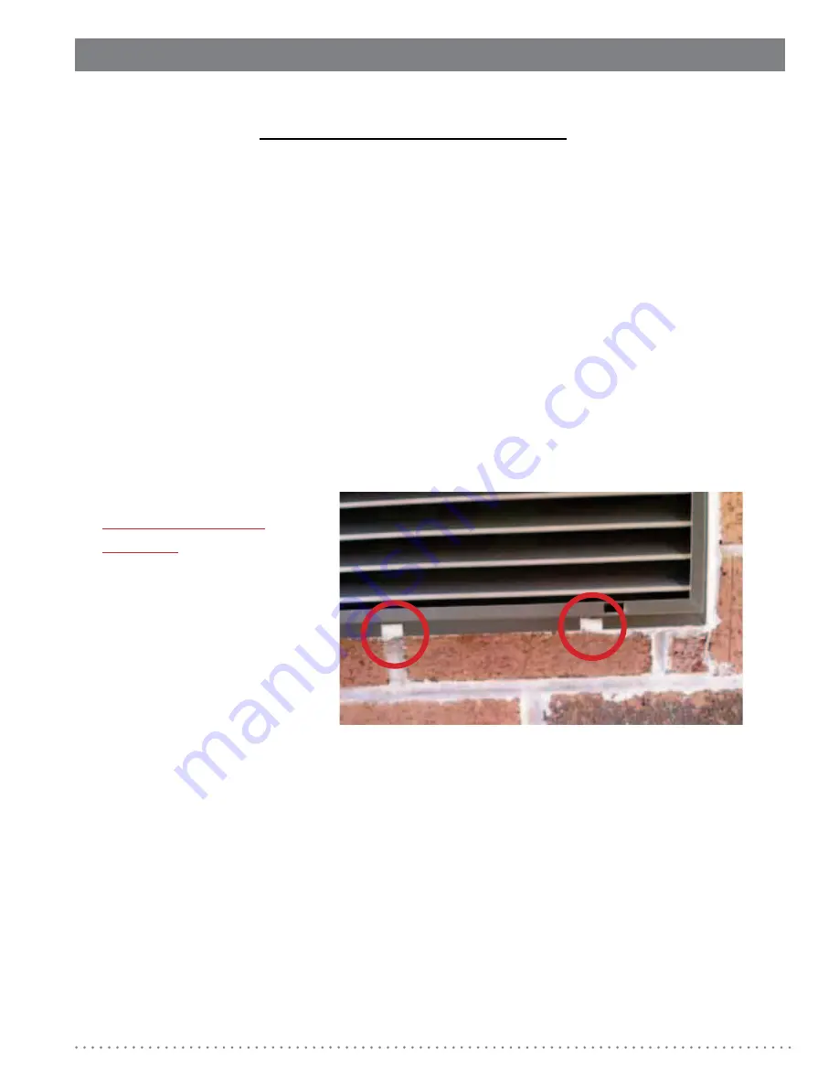
IMPORTANT:
WEEP HOLES MUST BE
LEFT OPEN
WHEN CAULKING
AND SEALING THE UNIT
FROM THE EXTERIOR.
(SHOWN AT RIGHT,
WEEP HOLES WERE
INCORRECTLY CAULKED
CLOSED)
Installation/Instruction Manual for Architects & Engineers
19.
Содержание Comfort Pack Electric
Страница 32: ...Notes Installation Instruction Manual for Architects Engineers 30 ...
Страница 33: ......


