7
The NL-RCV-RMPCUL Receiver is intended to operate in an
indoor dry central station environment. Temperatures above
95 degrees F, continuously high humidity, extremely dusty
conditions, and a corrosive atmosphere should be avoided.
The Receiver mounts onto a standard 19-inch rack. Refer to
the instructions included with the rack mount adapters.
Two Receivers can be interconnected and work in tandem.
The first machine to be powered up will configure itself as the
"Active Receiver". When the second machine is powered up,
it will automatically be configured as the "Hot Backup Re-
ceiver". In this manual, these two descriptions ("Active Re-
ceiver" and "Hot Backup Receiver") will be used to describe
the two components of Hot Backup operation.
Note:
After
both Receivers are powered up, the Active Receiver keypad
will light its green LED to distinguish between the Active Re-
ceiver and the Hot Backup Receiver.
ENCLOSURES
For the Receiver housing, UL requires the use of a listed
rack, cabinet, and wiring as described on page 3.
ROUTER SETUP
Please contact your IT personnel to assist you with configur-
ing the router. A UL listed ITE router containing at least 4
ports (such as NETGEAR Model WGR614NA Version 6.0
router) is recommended. (Do
NOT
use a switch or hub).
The Receiver is to be connected to a dedicated network and
not be attached to a corporate network backbone.
The router
must
be configured for port forwarding and must
port forward to the network address chosen for the Receiver
(s) (i.e. the IP address requested by the keypad when first
powered up--see page 8). One Virtual IP address is used for
both Receivers. The transmitters are defaulted to send
events to Port 5001, and the Receiver listening port must
match this port number, otherwise see page 23 to change the
Receiver port number. Also, be sure the router is port for-
warded to this number.
RECEIVER WIRING
To install the Receiver, follow the following simple instruc-
tions, and refer to the Installation Diagram below (each con-
nection is numbered in the diagram). All connections are
made at the rear of the Receiver.
INSTALLATION DIAGRAM
Refer to page 6 for a description of the Receiver rear hous-
ing, and plug in cables as follows:
1. CONNECT AC POWER INPUT CABLE
Position the Receiver within reach of a standard unswitched
110VAC outlet with a solid earth ground. Do not turn on Re-
ceiver yet--but simply connect the AC cord to each 110V AC
power input jack located at the back of each Receiver and
plug each power cord into an unswitched 110VAC outlet.
AGAIN, DO NOT TURN ON RECEIVER POWER AT THIS
TIME.
2. CONNECT AUTOMATION HOST COMPUTER
Connect the Receiver to a UL listed automation system. The
Automation
COM
port is configured by default for 9600-baud,
8 data bits, 1 stop bit, and no parity. The Service Application
software allows for reconfiguration of this port.
3. CONNECT PRINTER CABLES
Connect the printer to the
LPT1
parallel printer port.
DO
NOT connect ANYTHING to the LPT2 port
. After connect-
ing the printer AC power cord, apply power to printer.
Note:
UL Central Station applications must use a parallel printer
listed for Fire Protective Signaling Systems.
4. CONNECTING LAN1 TO THE ROUTER
Connect a standard RJ-45 connector into the
LAN1
socket
and the other end into the router. Do the same for the Hot
Backup Receiver (if used).
5. CONNECTING LAN2 - CROSSOVER CABLE
If
NOT
using a Hot Backup configuration,
skip this step
.
If you are using a Hot Backup configuration with two Receiv-
ers acting together, then connect one end of the RJ-45 cross-
over cable (e.g., NAPCO part #W943) to the
LAN2
socket of
one Receiver, and connect the other end of the same cross-
over cable to the
LAN2
socket of the other Receiver.
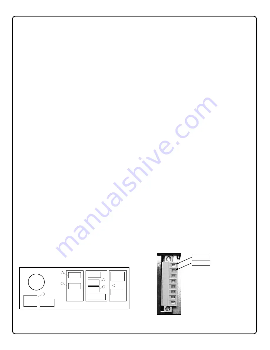
6. RELAY CARD CONNECTIONS
Connect the
Trouble Relay
terminals 1 and 2 to a notifica-
tion device. See image below for terminal locations.
Installation and Startup
Rear of the NL-RCV-RMPCUL Receiver
COM1
LPT1
(LPT2)
Trouble
Relay
(VIDEO)
LAN1
LAN2
(KEY/MOUSE)
COM Card
LAN Card
Relay Card
AC Power
Input
Connector
Main Power
Switch
Fan
1
4
6
3
5
2
Terminal 2
Terminal 1
Trouble Relay
Trouble Relay
- Maximum
4 Amps, 12VDC, resistive
relay.
Содержание Net.Link NL-RCV-RMPCUL
Страница 27: ...27 NOTES...


