15
SETTING UP THE EOP MODULES
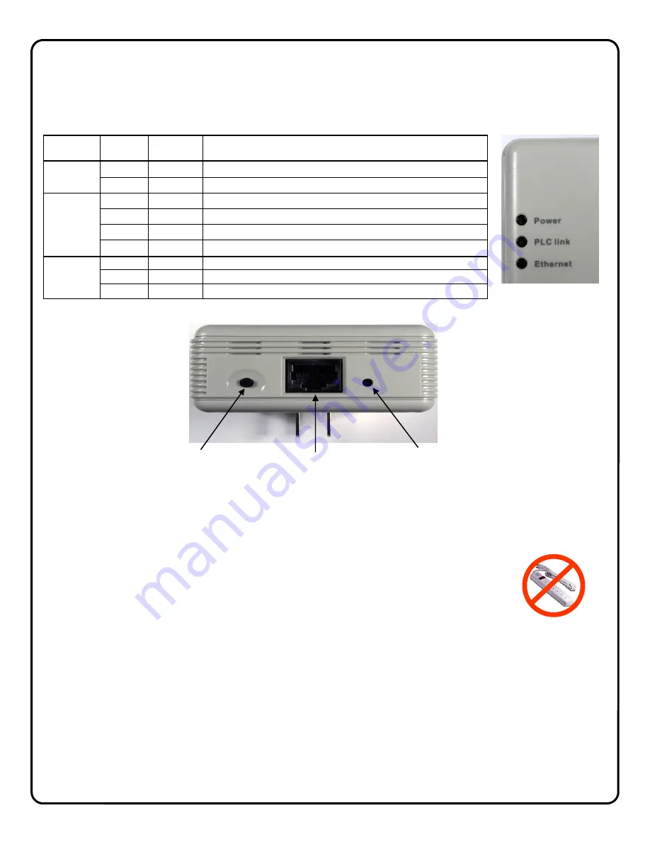
The ISEE-EOP MOD200 has three LED indicators on the front panel that display the EOP status.
Security Button
Press the Security Button to activate the AES encryption and create a secure network.
Please
refer
to
Creating a secure EOP network
section for more details.
LAN Port
Connect the device to the EOP module using provided RJ45 terminated CAT5 cable.
Reset Button
Press and hold the Reset Button to clear all data and restore settings to the factory default values.
SETUP
1
Connect the CAT5 cable from an EOP module to the camera and plug into AC wall socket.
2
Connect the CAT5 cable from an EOP module to the G-BOX and plug into AC wall socket.
3
Wait a minute for startup to be completed, and then check the LEDs
• The
Power
LED should be ON.
• The
PLC Link
LED will be ON if the other EOP modules are detected,
otherwise it will be OFF.
• The
Ethernet
LED should be ON.
LED
COLOR
STATE
STATUS
Power
Off
No power
Blue
On
Normal operation
PLC link
Blue
On
EOP network active - at least one other device detected
Blue
Flashing
Data receive rate greater than 80Mbps
Pink
Flashing
Data receive rate between 50 Mbps and 80Mbps
Off
EOP network not available - no other devices detected
Ethernet
Off
No Ethernet connection detected
Blue
On
Ethernet connection is active
Blue
Flashing
Data is being transmitted or received via the Ethernet Port
SECURITY
BUTTON
LAN
PORT
RESET
BUTTON
Note: If AC power-strips
are required due to un-
available AC outlets, non
surge protected or noise
filtered power-strips must
be used. Many AC power-
strips utilize internal surge
protection that may pre-
vent the EOP modules
from operating.
EOP module must
be plugged directly
into wall outlet


