


NAPCO Security Systems
GEM-P1632 Installation Instructions
WI808B 8/98
Page 19
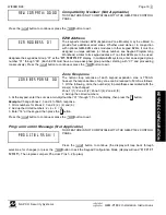
Compatibility Number (Not Applicable)
THIS FEATURE IS NOT COMPATIBLE WITH THE GEM-P1632 CONTROL
PANEL.
Press the
button to continue or press the
button to exit.
EZM Address
The keypad's internal EZM (Expansion Zone Module) may be utilized to
provide four additional wired zones. Whether used alone or in conjunction
with optional GEM-EZM series modules or other keypad EZMs, it must be
assigned a unique address (or Group number, see Keypad Programming
Workbook) similar to its keypad address. If no other EZMs are to be used,
designate the keypad as Group “01” at the “
” display. In multiple-EZM systems, enter an assigned group
number “01” through “06”. (Each EZM must have a unique assigned group number, starting with “01” and proceeding
consecutively.) Press the
button to continue or press the
button to exit.
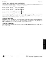
Zone Response
The normal loop response of each keypad expansion zone is 750mS,
however the response time of any zone can be reduced to 50mS as follows.
1. Of the following, circle the number(s) in parentheses associated with the
zone(s) to be changed:
Zone 1=(1); Zone 2=(2); Zone 3=(4); Zone 4=(8)
2. Add up the circled numbers.
3. At the keypad, enter the sum as a two-digit number “01” through “15” on the display, then press the
button.
Example.
Change Zones 2, 3 and 4 to 50mS response.
1. Circle numbers for Zones 2, 3 and 4: (2), (4) and (8).
2. Add up the circled numbers: 2 + 4 + 8 = 14.
3. Enter “14” at the keypad, then press the
button.
Press the
button to continue or press the
button to exit.
Program Control Message (Not Applicable)
THIS FEATURE IS NOT COMPATIBLE WITH THE GEM-P1632 CONTROL
PANEL.
Press the
button to continue (the display will loop back through
selections, for changes) or press the
button to exit the Keypad Configuration Mode (display will read “
”). Then replace Jumper JP5 across Pins 1–2 (top two).
KEYPA
D CONFIGURA
TION


