


3
Technical Manual
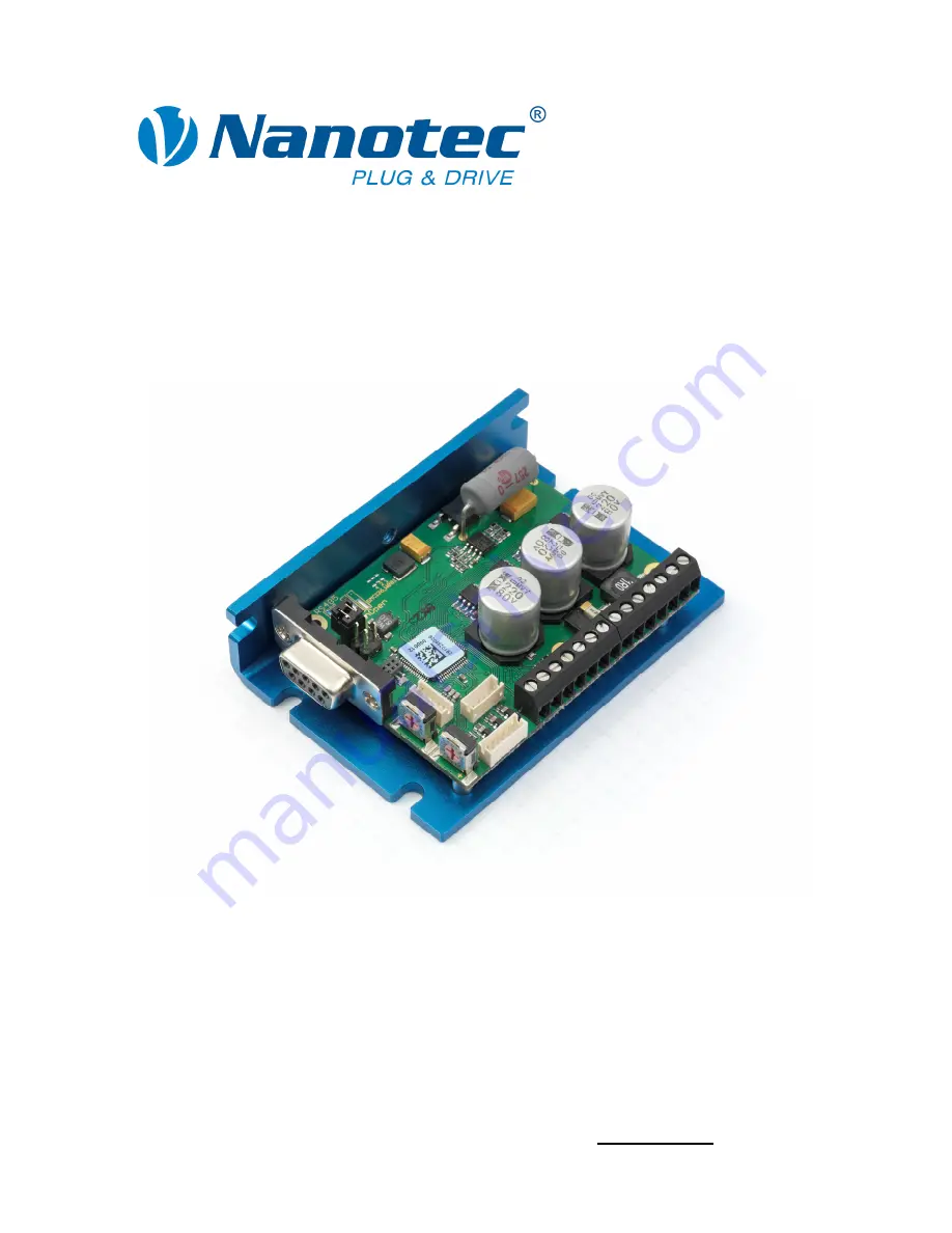
Controller for stepper and BLDC motors
SMCI36
NANOTEC ELECTRONIC GmbH & Co. KG
Gewerbestraße 11
D-85652 Landsham near Munich, Germany
Tel. +49 (0)89-900 686-0
Fax +49 (0)89-900 686-50
[email protected]
3
Technical Manual
Controller for stepper and BLDC motors
SMCI36
NANOTEC ELECTRONIC GmbH & Co. KG
Gewerbestraße 11
D-85652 Landsham near Munich, Germany
Tel. +49 (0)89-900 686-0
Fax +49 (0)89-900 686-50
[email protected]


