background image


Document # 720004-0000 
March 2, 2022 


21

Technicians Manual


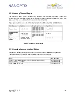
3.2  Ordering Thermal Paper 

 
The  following  paper  grade  produced  by  Appleton  and  Kanzaki  Specialty  Papers  are 
recommended  by  Nanoptix.  There  are  a  number  of  paper  converters  qualified  to  supply  this 
paper, provided the stacks are from these recommended grades. 
 
Paper qualification services are offered by Nanoptix for additional grades not listed below. 


Manufacturer 

Numbers 

Nanoptix part no.

Paper Grade 

Appvion Papers 

Tel:920-991-8438 

100505-3024R (200 stack) 
100505-3025R (400 stack) 
100505-3026R (600 stack) 
100505-3027R (800 stack)

Royale 800-4.5 

Kanzaki Specialty 
Papers 
(USA) 

 
Tel:888-526-9254 
Fax: 413-731-8864


100505-3012R (200 stack) 
100505-3013R (400 stack) 
100505-3014R (600 stack) 
100505-3015R (800 stack)

TO-381-N


Kanzan 
Spezialpapiere 
GmbH 

Tel: +49 2421 5924-0 
Fax: +49 2421 5924-19 

N/A 

KANZAN KL 69 


                                           Table 13: Ordering Thermal Paper 


3.3  Ordering Communication Cables 

 
Contact your sales representative to order the communication cables listed in the table. 
The numbers are for reference only. Suppliers may use other numbers.


Part 

Part Number 

RS232 communication cable (14-Pin “Molex” type to DB-9)

210036-0004R

OneCheck In-Line Cable 

210036-0003R

USB Cable 2M (A to B) 

100390-0001R


Содержание PayCheck

Страница 1: ...PayCheck PayCheck 2 PayCheck 3 PayCheck 4 Technicians Manual First Edition August 1 2006 Revision March 2022 Document 720004 0000 ...

Страница 2: ...ion Nanoptix is a trademark Other trademarks and registered trademarks are the property of their respective holders Federal Communications Commission FCC Radio Frequency Interference Statement Warning Changes or modifications to this unit not expressly approved by the party responsible for compliance could void the user s authority to operate the equipment Note This equipment has been tested and f...

Страница 3: ... UL Listed power supply with standard 60Hz 50Hz 100 240VAC input and 24VDC output equipped with AC line filtering over current and short circuit protection Use of this product with a power supply other than the Nanoptix Inc power supply will require you to test the power supply and Nanoptix Inc printer for FCC and CE mark certification Communication Interface Cable An approved Nanoptix interface c...

Страница 4: ...Performance Metrics 11 1 7 Clearing Jams 13 2 Troubleshooting the Printer 14 2 1 Basic Printer Operation 14 2 2 Communication Cables Pin Out 15 2 2 1 Universal Communication interface 15 2 2 2 Serial Interface Connection pin out 16 2 2 3 Illuminated bezel interface 16 2 3 Printing Problems 17 2 3 1 Main Controller PCB Connector Layout 18 3 Media and Supplies Guide 19 3 1 Thermal Paper Specificatio...

Страница 5: ...CIFICATIONS 20 FIGURE 17 MECHANICAL DIMENSIONS 25 FIGURE 18 MAIN BRACKET 26 FIGURE 19 TICKET TRAY 26 FIGURE 20 BASE PLATE 27 FIGURE 21 FLAT CABLE A 27 FIGURE 22 FLAT CABLE B 28 FIGURE 23 DAUGHTER PCB 29 FIGURE 24 PRINTING MECHANISM PAYCHECK 1 2 3 30 FIGURE 25 PRINTING MECHANISM PAYCHECK 4 31 FIGURE 26 MAIN PCB 32 FIGURE 27 PAPER GUIDE 33 FIGURE 28 PAPER GUIDE SENSOR PAYCHECK 1 2 3 34 FIGURE 29 PAP...

Страница 6: ... 8 TABLE 4 WATCH DOG JUMPER 9 TABLE 4 BEZEL CONTROL 9 TABLE 5 LED INFORMATION 10 TABLE 6 14 PIN RS232 SERIAL INTERFACE 15 TABLE 7 RS 232 SERIAL INTERFACE PIN OUT 16 TABLE 8 BEZEL INTERFACE 16 TABLE 9 TROUBLESHOOTING PRINTING PROBLEMS 17 TABLE 10 CONNECTOR FUNCTIONS 18 TABLE 11 PAPER SPECIFICATIONS 19 TABLE 12 ORDERING THERMAL PAPER 21 ...

Страница 7: ...x PayCheck printer is extremely fast quiet and very reliable With thermal printing technology there is no ribbon cassette to change and paper loading is extremely simple The printer is small enough to fit almost anywhere and is easy to use with the ticket exiting from the front Figure 1 Nanoptix PayCheck Printer ...

Страница 8: ... defined Integrated Bar Codes UPC A UPC E interleaved 2 of 5 Code 39 Code 93 Codabar EAN 8 EAN 13 Code 128 Note Other Bar Codes can be programmed quickly Speed PayCheck PayCheck 2 Up to 125 mm sec monochrome PayCheck 3 PayCheck 4 Up to 200 mm 8 in per sec monochrome Up to 125 mm 5 in per sec two color mode Sensors Paper low paper out ticket taken drawer open ticket jam ticket in chute black mark D...

Страница 9: ...pt data from the host computer Since the printer cannot print any transactions the data may be lost The maximum stack that will fit in the ticket cartridge is 200 400 600 or 800 tickets depending on the cartridge option that was purchased with the printer Ticket stack orientation The stack must be oriented so that it s top of form mark is on the leading edge of the ticket Figure 2 Ticket Stack Ori...

Страница 10: ...22 4 Technicians Manual Open drawer Drop ticket stack into ticket if necessary cartridge Feed ticket into printer mechanism Once paper has been aligned until resistance is felt ticket is ready to print Figure 3 Loading Paper C D A B ...

Страница 11: ...fication Connector Type Function A 14 pin Molex type Power dual serial communication B USB type B USB communication C USB type B USB maintenance D 3 pin Molex type Bezel illumination Table 2 Interface Ports Figure 4 Interface Ports D 3 pin Molex type C USB type B A 14 pin Molex type B USB type B ...

Страница 12: ...ecting and reconnecting the power communication cable Once connected the printer goes through a startup routine and resets itself Figure 5 Printer Reset 1 5 2 Paper Feed Button The paper feed button is used to advance the paper Once the ticket removed the printer will realign the paper to the ready position Paper Feed Figure 6 Paper Feed Button ...

Страница 13: ...s the firmware selector DIP switches PayCheck 4 DIP switch is available through access hole in paper tray Various firmware and setting configurations are available by selecting the 16 different DIP switch combinations Applies to PayCheck 3 PayCheck 4 only Figure 7 F W DIP Switch DIP switch functions vary in different firmware versions ...

Страница 14: ...ctor DIP switches PayCheck 4 Remove ticket tray plate to access the boot mode selector DIP switches Different boot options are available by selecting the 4 different DIP switch combinations Figure 8 Boot Selector DIP switch settings Function OFF OFF Run mode default setting OFF ON Future ON OFF Future ON ON Recovery mode Corrupted firmware Table 3 Boot Selector ...

Страница 15: ...nction ON Run mode default setting OFF Recovery mode disable watch dog Table 4 Watch Dog jumper 1 5 6 Bezel illumination control jumper Figure 10 Bezel Control Jumper setting Function ON Bezel illumination control connected to pin 9 of host I O OFF Bezel illumination control not available on Pin 9 of host I O Table 5 Bezel Control 1 5 7 LED ...

Страница 16: ... LED Green Voltage LED Red PayCheck 2 only Condition OFF ON OFF Printer Ready ON OFF OFF Paper Out MED BLINK OFF OFF Temperature Error SLOW BLINK OFF ON Bright Voltage Error Over 26 2 VDC FAST BLINK ON OFF Print Head Error FAST BLINK ON OFF Missing Black Index Mark FAST BLINK ON OFF Paper Jam Table 6 LED Information Error LED Status LED Voltage LED RED GREEN RED PayCheck 2 only Figure 11 LED Posit...

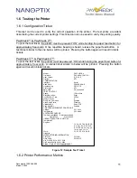
Страница 17: ... will be printed Pressing the button again will result in blank tickets Figure 12 Sample Test Ticket 1 6 2 Printer Performance Metrics Model PAYCHECK 4 Firmware PAY 4 82H 0x1CB1 User Version S R 2 4 0 Protocol NTL COMMUNICATION Interface Serial Baud Rate 38400 8 NONE Handshaking PRT RTS Print mode NTL Back USB Fw Controlled PRINT CONTROL Speed 100 mm sec Black Bar Index Right No HPQ Burn Time 250 ...

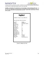
Страница 18: ...old the paper feed button for approximately 5 seconds A performance ticket similar to below will be printed Figure 13 Sample Test Ticket B8D52E31 Performance Report B8D52E31 Nanoptix Paycheck USB printer Statistics Printer ID P4B3671 Model PAYCHECK 4 Firmware N4U00512Q 0x9D8A Power Cycles 39 Tickets printed 2906 Jams 2 Voltage errors 0 TOF Errors 1 Drawer opened 57 Paper low 46 Paper out 23 Platen...

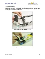
Страница 19: ...echnicians Manual 1 7 Clearing Jams The Nanoptix PayCheck printer s paper guide and printing mechanism roller are easily removed giving full access to the paper path Figure 14 Clearing Jams PayCheck 1 2 3 Figure 15 Clearing Jams PayCheck 4 ...

Страница 20: ...The two main components of the printer the base assembly and the main bracket are connected together via a white flat cable A photo interruptible sensor D is used to detect the main bracket s pocketed open close status A reflective optical sensor B situated at the front of the ticket tray is used to detect a low paper condition On newer models of the Paycheck the paper low detection has been moved...

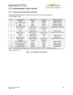
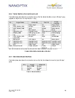
Страница 21: ...rame Ground 6 24V Power Input n a Power Input 7 Signal Frame Ground Signal Frame Ground Signal Frame Ground Signal Frame Ground 8 24V Power Input n a Power Input 9 Bezel_pwm 24V Output n a Bezel Driver 10 Signal Frame Ground Signal Frame Ground Signal Frame Ground Signal Frame Ground 11 PRT_RS232_RXD Input Output Data Receive 12 PRT_RS232_TXD Output Input Data Transmit 13 PRT_Status Output Input P...

Страница 22: ...p to 24V Input Printer Ready 7 n a No connect n a none 8 PRT_RS232_RTS host CTS Output Input Handshake 9 Bezel pwm 24V Output n a Bezel driver 10 Signal Ground Signal Ground Signal Ground Signal Ground 11 Signal Ground Signal Ground Signal Ground Signal Ground 12 24V Power Input n a Power Input Shell Frame Ground Frame Ground Frame Ground Shield Note Bezel illumination control jumper must be prese...

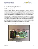
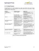
Страница 23: ...ed with paper engaged in the printing mechanism failing to do so will cause gears to grind and slip noise may result Do not operate printer without any paper engaged in the printing mechanism Note Never lubricate gears or any other part of the printer Paper does not realign itself when a ticket is printed Paper s alignment mark which is the black dot printed on the non sensitive side of thermal pa...

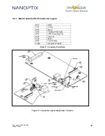
Страница 24: ...2 3 1 Main Controller PCB Connector Layout J100 USB J101 Future J200 Bezel J300 Thermal Print Head J301 TPH Grounding Tab J400 Paper In J700 Motor J800 Top Of Form J1000 Daughter PCB I O Table 11 Connector Functions Figure 17 Connector Layout PayCheck shown ...

Страница 25: ...al paper with the following specifications is required for proper operation Width 65 mm 1 2 56 IN Length 156 mm 1 6 14 IN Thickness 4 5 0 1 0 3 mil Brightness 89 Smoothness 2000 sec Avg Perforation burst strength 1 3 0 4 LBS 0 59 0 18 Kg Alignment Mark TOF Optical Density 1 10 min Table 12 Paper Specifications Figure 18 Perforation Test ...

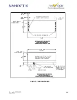
Страница 26: ...Document 720004 0000 March 2 2022 20 Technicians Manual Figure 19 Ticket Specifications ...

Страница 27: ...ack 100505 3025R 400 stack 100505 3026R 600 stack 100505 3027R 800 stack Royale 800 4 5 Kanzaki Specialty Papers USA Tel 888 526 9254 Fax 413 731 8864 100505 3012R 200 stack 100505 3013R 400 stack 100505 3014R 600 stack 100505 3015R 800 stack TO 381 N Kanzan Spezialpapiere GmbH Tel 49 2421 5924 0 Fax 49 2421 5924 19 N A KANZAN KL 69 Table 13 Ordering Thermal Paper 3 3 Ordering Communication Cables...

Страница 28: ...Document 720004 0000 March 2 2022 22 Technicians Manual 3 4 Parts List ...

Страница 29: ...rconnect reorder 102971 02 01 22 103490 0001 Bezel 65mm Long Green 22 103490 0002 Bezel 65mm Long Blue 23 100795 0000 Ticket Chute Lock 24 100069 1001 Torsion Spring Left 25 100417 0000 Upper Paper Chute 26 100612 0000 Lower Ticket Chute 27 100069 2003 Compression Spring 0 625 Long 28 100350 0001 Axiohm MHTP Mechanism FS24 80mm Default 29 100041 1166 M3 x 10mm SEMS Screw Mech 30 100069 1002 Torsio...

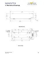
Страница 30: ...Document 720004 0000 March 2 2022 24 Technicians Manual 4 Mechanical Drawings Right Side View Bottom View ...

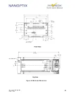
Страница 31: ...Document 720004 0000 March 2 2022 25 Technicians Manual Front View Top View Figure 20 Mechanical Dimensions ...

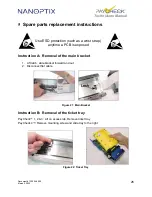
Страница 32: ...et 1 Lift latch slide bracket forward and out 2 Disconnect flat cable Figure 21 Main Bracket Instruction B Removal of the ticket tray PayCheck 1 2 3 Lift on access tab Remove ticket tray PayCheck 4 Remove mounting screw and slide tray to the right Figure 22 Ticket Tray Use ESD protection such as a wrist strap anytime a PCB is exposed ...

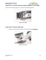
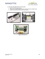
Страница 33: ...oval of the base plate PayCheck 1 2 3 only Remove Tinnerman screw using inch nut driver and slide base plate back Figure 23 Base Plate Instruction D Removal of flat cable 1 Disconnect the main controller PCB end of the cable by following Instruction A Figure 24 Flat Cable A ...

Страница 34: ...hnicians Manual 2 Disconnect daughter PCB end of the cable 1 Remove the two cable retainers 2 Remove the universal daughter PCB by removing the four mounting screws 3 Unlatch cable by lifting the two side connector tabs Figure 25 Flat Cable B ...

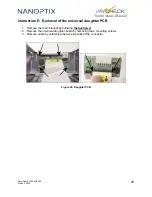
Страница 35: ...truction E Removal of the universal daughter PCB 1 Remove the main bracket by following Instruction A 2 Remove the universal daughter board by removing the 4 mounting screws 3 Remove cable by unlatching the two side tabs of the connector Figure 26 Daughter PCB ...

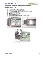
Страница 36: ... tray by following Instruction B 2 Remove base plate by following Instruction C 3 Disconnect the TOF flex circuit and printing mechanism flat cable 4 Remove the 2 mounting screws 5 Lift printing mechanism straight up 6 Disconnect motor connector 7 Disconnect mech grounding tab using long nose pliers Figure 27 Printing Mechanism PayCheck 1 2 3 ...

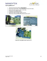
Страница 37: ...2 Disconnect the TOF flex circuit and printing mechanism flat cable 3 Remove the blue top paper guide not shown 4 Remove the 2 mounting screws 5 Lift printing mechanism straight up 6 Disconnect motor and paper guide connector 7 Disconnect mech grounding tab using long nose pliers Figure 28 Printing Mechanism PayCheck 4 ...

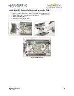
Страница 38: ...echnicians Manual Instruction G Removal of the main controller PCB 1 Remove the printing mechanism kit by following Instruction F 2 Disconnect bezel paper guide harnesses 3 Disconnect flat cable 4 Remove 4 mounting screws Figure 29 Main PCB ...

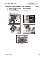
Страница 39: ...ove the printing mechanism kit by following Instruction F 2 Pry one side and hold 3 Keeping an upwards pressure push on the other side s tab 4 Then remove by unlatching the final 2 tabs Note during reassembly make sure to install the right spring on the right side and the left spring on the left side Figure 30 Paper Guide ...

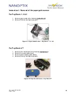
Страница 40: ...er guide kit by following Instruction H 2 Remove PCB by carefully prying latch Figure 31 Paper Guide Sensor PayCheck 1 2 3 For PayCheck 4 1 Remove print mechanism kit by following Instruction F 2 Remove top paper guide blue 3 Remove bottom paper guide black 4 Remove PCB by carefully prying latch Figure 32 Paper Guide Sensor PayCheck 4 ...

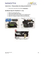
Страница 41: ...m kit by following Instruction F Additional steps for PayCheck 4 only 2 Remove top paper guide blue 3 Remove bottom paper guide black 4 Remove the Axiohm mount by remove the 2 mounting screws 5 Remove the mech mount by removing the mounting screw 6 Remove Front Axiohm module by removing mounting screw Figure 33 Mech Kit PayCheck 4 ...

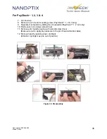
Страница 42: ... only 9 Separate mechanism by sliding mount upwards PayCheck 1 2 3 only 10 Push sensor out using a screw driver 11 Remove print head by prying with a small screw driver Make sure not to apply any pressure to the print head white flat cable 12 Remove head by pushing down and back Attention springs may pop out of position Figure 34 Disassembly ...

Страница 43: ...itions the minimum interval for cleaning the Nanoptix PayCheck printer is 3 months or 5 km of paper printed which ever comes first 1 Slide printer drawer open and remove ticket tray Figure 35 Remove Ticket Tray 2 Remove excess dust using a portable vacuum cleaner or wipe clean with a damp cloth Figure 36 Remove excess dust ...

Страница 44: ... on the TOF sensor area Figure 37 Clean TOF sensor 4 Remove paper guide cover when in use top paper guide Then press down on bottom paper guide Figure 38 Remove top paper guide 5 Remove roller by pressing down and rolling out towards front of printer Figure 39 Remove Roller ...

Страница 45: ...using cotton swab Figure 41 Clean paper guide sensor using cotton swab 8 Make sure that bottom paper guide can move up and down freely Ensure that the gaps pointed by the arrows are equal and measures approximately a millimeter 20 mils or the thickness of 5 sheets of TITO paper If not readjust the frame to ensure proper alignment Figure 42 Bottom paper guide inspection ...

Страница 46: ...If excessive wear is visible deep grooves caused by paper bottom paper guide should be replaced Good Replace 10 Remove dust from gear using brush Figure 43 Remove dust from gears using brush 11 Clean the heating elements black line on the print head with a cotton swab and isopropyl alcohol Figure 44 Clean Heating Elements ...

Страница 47: ...t the RMA number is clearly visible on the outside of each package being sent NOTE Make sure to place a blank ticket or a piece of paper between thermal print head and roller for shipping and storage Ship to address RMA XXXXXX Nanoptix Inc 699 Champlain St Dieppe NB Canada E1A 1P6 7 2 Technical Support Contact Information Service department Nanoptix Inc 699 Champlain St Dieppe NB Canada E1A 1P6 Te...
Отзывы: