8
8
I
Warning! :
Your engine must be installed by an authorised shipyard or a qualifi ed Nanni Industries representative in
accordance with the on board assembly instructions.
However, you can check some important points on the installation of the engine. However, your installation can be different
than the one that is indicated in this chapter.
6
7
4
3
5
1
2
waterline
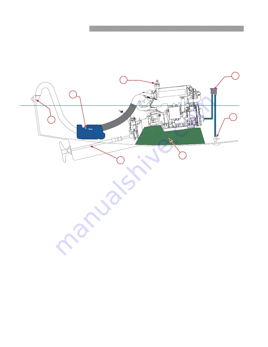
Installation inspection
1. Engine frame
The engine frame must be solid and able to absorb all
the dynamic stress as well as the weight of the engine. It
must be connected to the hull by a big a surface area as
possible.
The engine must not be at an angle of more than 7° when
the boat is stopped.
2. Propeller shaft
The choice of propulsion system must be made according
to the restrictions arising from the engine and the boat.
3. Water exhaust box (waterlock)
The waterlock must be positioned as close to the engine
and as low as possible. Its volume must be of 20 litres
minimum. The maximum allowable back pressure is 28.7
kPa (4.162 PSI)
4. Hull outlet
The hull outlet must be located 15 cm above the water line.
The tube between the exhaust box and the hull outlet must
form a swan-neck shape to avoid any water getting into the
exhaust system through the hull outlet.
5. Anti-siphon valve
This is obligatory on boats whose engine is below the
waterline. The anti-siphon valve must be installed at the
end of the seawater system before injection in the exhaust
elbow and must be positioned above the waterline, between
0.5 and 2 meters.
6. Seawater fi lter
This must always be positioned at least 15 cm above the
waterline.
7. Through-hull valve
On yachts and boats that do not go above 12 knots, the
water inlet must be turned towards the end of the boat.
On motor boats that go over 12 knots, the water inlet must
be turned forwards.
Engine room
The temperature inside the engine compartment must not
exceed 50°C with a maximum difference of 20°C with the
outside temperature.
Slow boats must have a ventilator fi tted. Fresh air from the
front is circulated from front to back. The front air intake is
located low down at the front of the engine compartment
and the outlet high at the back for optimum air circulation
(air needed : T4.200 : 1520 m
3
/h, T4.180 : 1370 m
3
/h,
T4.165 : 1260 m
3
/h).
The cables and extensions must be securely fastened to
the engine and / or on the walls of the engine room (do
not let it dangle in the hold or let it exposed to water or
moisture).


