
6
6
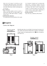
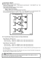
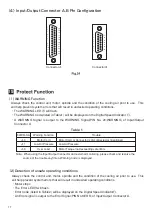
Diagrams
Control Unit Diagram
Fig.3
Fig.4
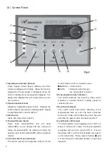
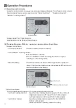
When any of the yellow or red LEDs are lit the
warning LED (Warning) ⑳ will flash, if this condition
is continued beyond the allowable interval the error
LED (Error) ⑲ will flash and the motor/spindle will
be shut down.
⑲
Error LED (Error)
When a serious problem with the system is
detected this LED blinks, the motor/spindle is shut
down and the Digital Speed Indicator ⑪ displays
the error code.
⑳
WARNING LED (WARNING)
The operating and working conditions of the system
are constantly monitored and the warning LED
blinks when a hazardous condition has been
detected. When a hazardous condition is detected
the warning LED blinks and the Digital Speed
Indicator ⑪ alternates between the warning code
and the actual or preset speed, depending on
whether or not the motor/spindle is rotating.
@1
Rotating LED (RUN)
When the motor is rotating this LED will flash.
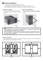
Mounting brackets are provided for mounting the control unit.
The control unit can be mounted either vertically or horizontally.
Please review the mounting cautions on P9
⁄00
prior to mounting
the control unit.
Brackets installed
on the bottom
207.6
193.8
25
20
219.8
68
108
174.8
25
25
156
174.8
10
206
10
156
108
4.5
4.5
68
Brackets installed
on the rear